Electric alternator for wind power generators

a technology electric alternators, which is applied in the direction of wind power generation, motors, dynamo-electric machines, etc., can solve the problems of mechanical losses, typical failure events, and subject to failure, and achieve the effect of simplifying the structure of wind power generators

Inactive Publication Date: 2012-06-14
ENATEK
View PDF3 Cites 12 Cited by
  • Summary
  • Abstract
  • Description
  • Claims
  • Application Information

AI Technical Summary

Benefits of technology

[0009]An important object of the invention is to allow to simplify the structure of a wind power generator with blades whose direction of overall development follows substantially the direction of development of the axis of rotation of the generator / alternator.
[0010]Another important object of the invention is to provide a wind power generator with an electric alternator, like the ones described above, that can cooperate to a reduction of the risks of failure of the structure of the generator to which the electric alternator it is applied.
[0014]Advantageously, with an electric alternator of this type, it is possible for example to simplify the structure of the generator to which the alternator is applied. In fact, whilst the structure of a traditional wind power generator with vertical / horizontal axis with blades having axial development normally comprises a rotating shaft, a certain number of wind blades and the related spokes anchoring to the rotation shaft whereon the alternator will then be keyed, the structure of a generator with alternator according to the invention instead is simplified with respect to the fixing of the spokes: the alternator according to the invention becomes the support of the anchoring spokes of the blades.
[0015]Conveniently, if a greater production of electrical energy is to be obtained, it will be possible to associate to the axis of rotation of the wind power generator multiple alternators which, carrying supporting arms of the blades will contribute to reinforce the support of the wind blades.
[0026]This structure of the alternator allows considerable ease of assembly and it also significantly facilitates the composition of the wind power generator. In fact, on at least one of the two opposite parts that form the rotor of the alternator can advantageously be provided fixing positions for the support means of the blades of the wind power generator, like for example radial arms at whose ends the blades are fixed. Alternatively, this part of the rotor can be constructed in a single piece with the supporting arms of the blades.
[0028]An alternator structure thus described is particularly advantageous combined with a wind power generator. Obviously, the structure of the alternator linked to the simplicity of assembly can be considered useful even if it is not combined with the direct support of the blades, being usable along the axis of the rotor to increase the electrical power produced without necessarily having to support the blades, or being otherwise used in other fields of electrical energy production.

Problems solved by technology

The connection of the shaft of the structure with the wind blades to the alternator takes place through appropriate connecting members which, as is obvious, produce mechanical losses and are subject to failures in case of excessive loads.
A typical failure event can take place in the case of an unbalanced rotary load, due for example to the failure or to the deformation of a blade, a support spoke, a bearing or other.
It will be difficult for this alternator to be exploited for generators of a different power rating.
The assembly of wind power generators of the type with blades that follow the development of the axis of rotation is certainly more complicated than the assembly of generators with radial blades, in virtue of the plurality of support spokes that need to be positioned between the rotating shaft and the blades.
Such spokes, although in theory they are designed with the utmost care, constitute unbalanced rotating masses, often because of deformations of the spokes themselves and of the presence of connecting / fixing members between the spokes, blades and shafts etc., not adequately considered during the design stage.

Method used


Image

  • Electric alternator for wind power generators
  • Electric alternator for wind power generators
  • Electric alternator for wind power generators

Examples


Embodiment Construction

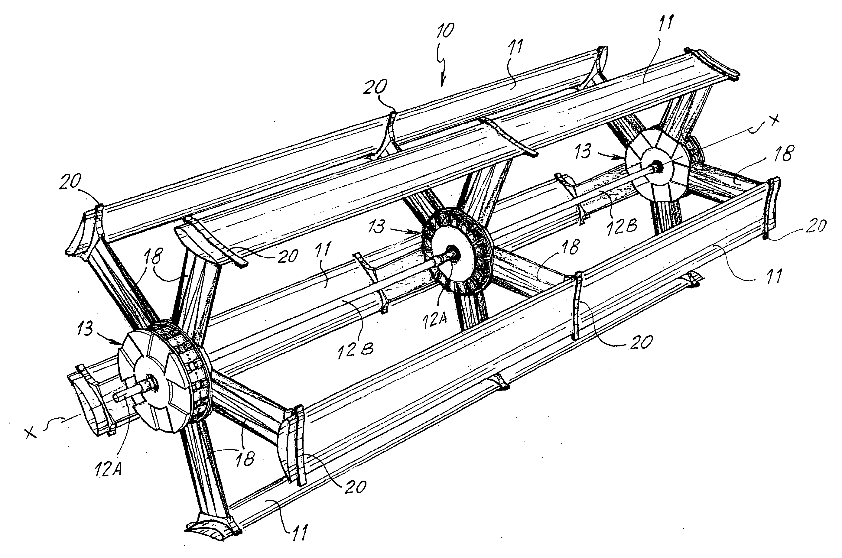
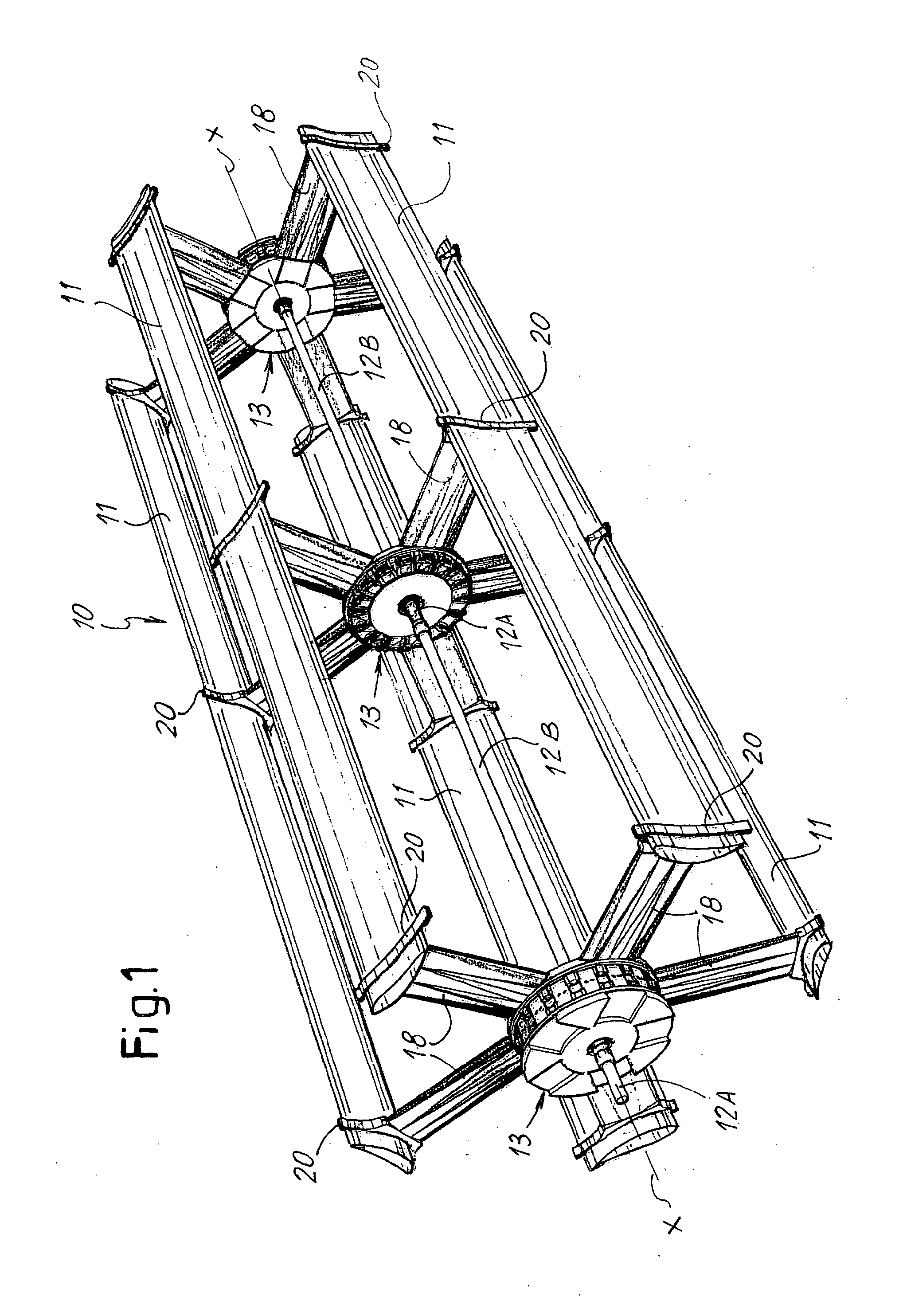
[0064]With reference to the aforementioned figures, a wind power generator according to the invention is schematically represented by its blade structure and it is indicated as a whole in FIG. 1 with the number 10. This wind power generator 10 is of the type with blades 11 whose direction of overall development substantially follows the direction of development of the axis of rotation X of the generator. In this example, the blades have rectilinear development with wing profile; clearly, in other embodiments these blades may for example follow the trend of the axis of rotation according to a helical development or yet they may be non continuous because they are constituted by mutually aligned sectors according to a preferred configuration, in any case always overall following the development of the axis of rotation. Obviously, also the shape of the profile may be the one best suited to the requirements.

[0065]The wind power generator 10, in this example, comprises an axial support wh...


PUM


Abstract

Wind power generator (10) with electrical alternator (13), of the type with blades whose direction of overall development follows substantially the direction of development of the axis of rotation (X) of the generator / alternator; said alternator comprising a rotor (15), forming the armature or the inductor of the alternator (13), designed to form at least in part the support structure (18, 19) for the blades (11) of the wind power generator (10) to which the alternator (13) is associated.

Description

CROSS REFERENCE TO RELATED APPLICATIONS[0001]This application is a United States National Phase application of International Application PCT / IT2010 / 000348 and claims the benefit of priority under 35 U.S.C. §119 of Italian Patent Application FI2009A000185 filed Aug. 11, 2009, the entire contents of which are incorporated herein by reference.FIELD OF THE INVENTION[0002]The present invention relates to the field of the production of electrical energy by means of wind power generators, and more in particular it refers to a wind power generator with electric alternator, of the type with blades presenting a direction of overall development that substantially follows the direction of development of its own axis of rotation, i.e. the axis of rotation of the generator / alternator.BACKGROUND OF THE INVENTION[0003]As is well known, wind power generators can be divided into two types, those with axis of horizontal rotation with the blades radial relative to the axis itself, optimized to meet the...

Claims


Application Information

Patent Timeline
Patent Type & Authority Applications(United States)
IPC IPC(8): F03D9/00
CPCF03D9/002F05B2220/7068Y02E10/725H02K7/183H02K21/24F05B2240/221F03D9/25Y02E10/728Y02E10/72F03D17/00F03D13/20
Inventor TEGLIA, GIOVANNI
Owner ENATEK
Why Eureka
Try Eureka