Sine-wave current line-start three-phase rare-earth permanent magnet synchronous motor

a permanent magnet, sinusoidal current technology, applied in synchronous motors, dynamo-electric machines, electrical apparatus, etc., can solve the problems of severe waste of electric energy, low practical operational efficiency, and low power consumption of all kinds of motors, and achieve excellent sinusoidal current during the operation of the motor, enhance the start performance of the motor, and simple rotor structure.

Inactive Publication Date: 2012-06-14
HUBEI SEEPOMOTOR SCI & TECH
View PDF3 Cites 6 Cited by
  • Summary
  • Abstract
  • Description
  • Claims
  • Application Information

AI Technical Summary

Benefits of technology

[0015]1. The pole face of the rotor of the present invention includes P pairs of poles (2P poles), each pole includes one polar arced surface, and a plane exists between adjacent polar arced surfaces, so that an uneven air gap is formed between the pole face of the rotor and the inner circular surface of the stator. According to the present invention, the characteristic of the salient pole structure of the uneven air gap is utilized to counteract the asymmetry of the magnetic paths caused by the permanent magnet, so that the asymmetry of the magnetic paths is improved, which makes the fabrication process of the rotor structure simple. Further, negative sequence components of the rotor current in the self-starting process of the motor can greatly be reduced, thereby enhancing the start performance of the motor, and meanwhile achieving an excellent sinusoidal current during the operation of the motor. Accordingly, the harmonic loss is reduced and the efficiency of the motor is enhanced.
[0016]2. By adjusting the ratio of the arced surface portion and the plane portion of the rotor pole face and the size of the air gap, an excellent sinusoidal magnetic flux density can be obtained, so as to further reduce the negative sequence components of the rotor current in the self-starting process of the motor and improve a start performance of the motor, and meanwhile to achieve an excellent sinusoidal current during the operation of the motor, so that the harmonic loss is further reduced and the efficiency of the motor is further enhanced.

Problems solved by technology

Currently, in China, the power consumption of all kinds of motors is about 70% of the domestic total power generation capacity.
Most of the motors are three-phase asynchronous motors that are directly operated in the grids, but the practical operational efficiency is generally very low and the electric energy is severely wasted.
However, the self-starting three-phase rare-earth permanent magnet synchronous motor because of its complexity has failed to achieve desirable advances.
The major cause is that there are a large amount of harmonics in the current resulted from conventional designs of the magnetic path of a motor, which affects the starting performance of the motor on one hand and greatly increases the loss during the operation of the motor on the other hand, whereby that the efficiency of the motor is decreased and the power saving potential of the motor is not fully exerted.
Furthermore, the large amount of harmonics in the current may also severely pollute to the grids.
At present, although people have already done a lot of work on enhancing and improving the structural performance of a self-starting three-phase rare-earth permanent magnet synchronous motor, a good sinusoidal current waveform is still unable to be obtained and the harmonic problem is still not completely solved.
ZL00252876.2, entitled “SINUSOIDAL PERMANENT MAGNET MAGNETIC FLUX DENSITY WAVEFORM PERMANENT MAGNET SYNCHRONOUS MOTOR”, an uneven air gap is realized through eccentricity between an inner circle of the stator and an external circle of the rotor of the motor, so as to improve a magnetic flux density waveform, but still cannot effectively improve the symmetry of a magnetic path and obtain a good sinusoidal current.
Therefore, a heretofore unaddressed need exists in the art to address the aforementioned deficiencies and inadequacies.

Method used


Image

  • Sine-wave current line-start three-phase rare-earth permanent magnet synchronous motor
  • Sine-wave current line-start three-phase rare-earth permanent magnet synchronous motor
  • Sine-wave current line-start three-phase rare-earth permanent magnet synchronous motor

Examples


Embodiment Construction

[0025]The present invention is more particularly described in the following examples that are intended as illustrative only since numerous modifications and variations therein will be apparent to those skilled in the art. Various embodiments of the invention are now described in detail. In accordance with the purposes of this invention, as embodied and broadly described herein, this invention, in one aspect, relates to a sinusoidal (or sine-wave) current line-start (or self-starting) three-phase rare-earth permanent magnet synchronous motor.

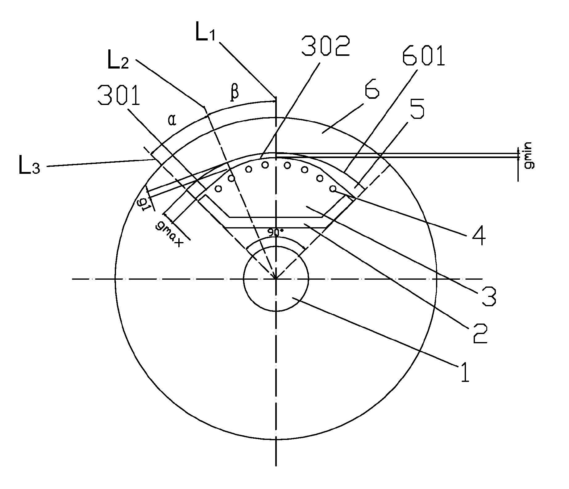
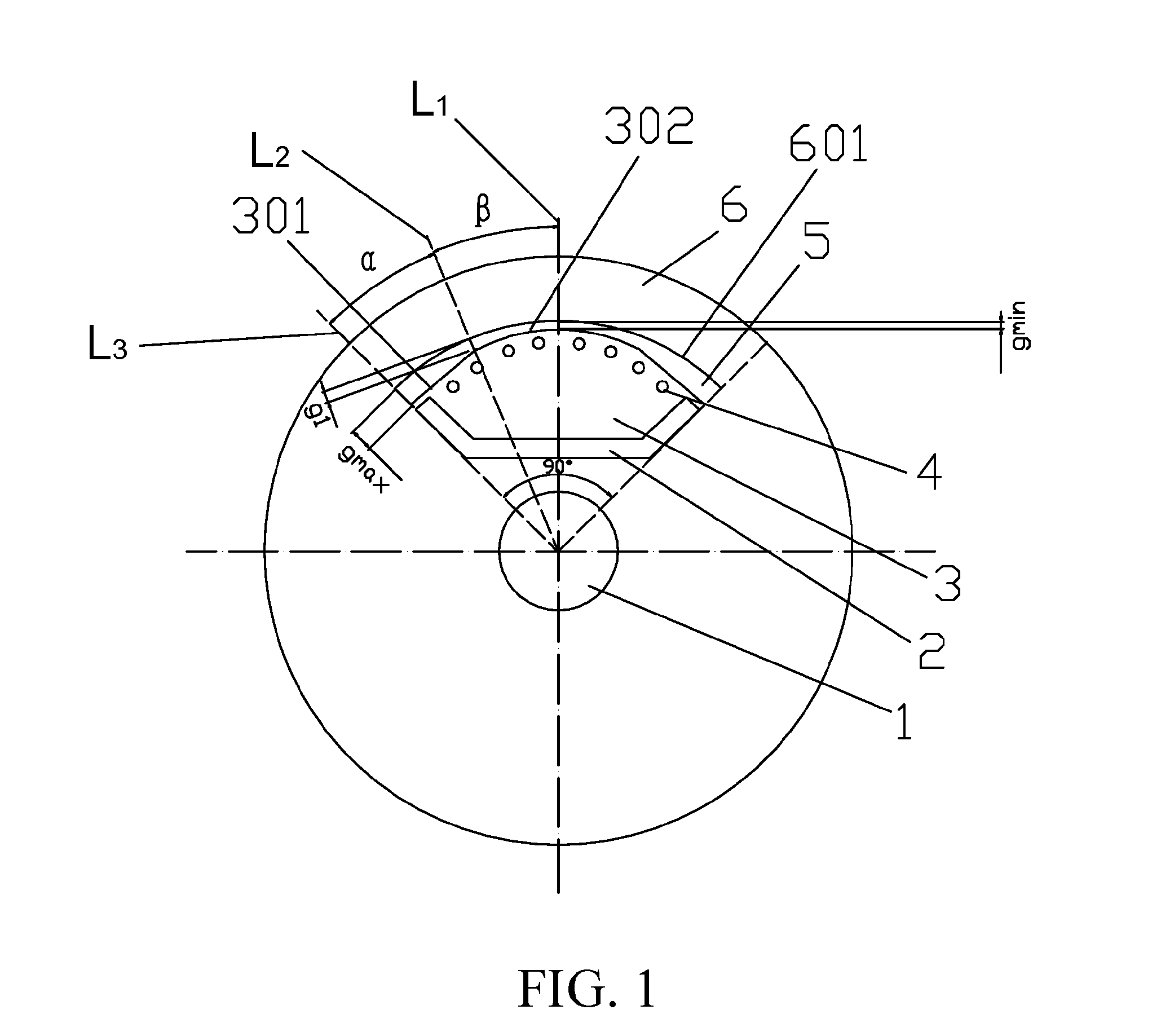
[0026]Referring to FIG. 1, a sinusoidal current line-start three-phase rare-earth permanent magnet synchronous motor is schematically shown according to one embodiment of the present invention. In the embodiment, the sinusoidal current line-start three-phase rare-earth permanent magnet synchronous motor includes a motor shaft 1, a rare-earth permanent magnet 2, a rotor (a rotor iron core) 3, rotor starting windings 4, an uneven air gap 5, and a s...


PUM


Abstract

A sine-wave current line-start three-phase rare-earth permanent magnet synchronous motor includes a motor shaft, a rotor and a stator. The rotor is disposed inside the stator and rotates around the motor shaft. The rotor includes P pairs of poles. Each pole includes a polar arched surface. A planar surface is formed between adjacent polar arched surfaces. Thus, a non-uniform air gap is formed between the pole face of the rotor and the inner circumferential surface of the stator. By the use of a salient-pole structure with the non-uniform air gap, the asymmetry of the magnetic circuit caused by permanent magnets can be offset, thereby making the manufacturing process of the rotor simplified, the negative sequence components of the rotor current during the line starting process reduced significantly, the starting performance improved, the sine-wave current provided during the operating process, the harmonic loss reduced, and the motor efficiency enhanced.

Description

FIELD OF THE INVENTION[0001]The present invention generally relates to a permanent magnet motor, and more particularly, to a self-starting three-phase rare-earth permanent magnet synchronous motor having a sinusoidal current.BACKGROUND OF THE INVENTION[0002]Currently, in China, the power consumption of all kinds of motors is about 70% of the domestic total power generation capacity. Most of the motors are three-phase asynchronous motors that are directly operated in the grids, but the practical operational efficiency is generally very low and the electric energy is severely wasted. Therefore, as long as the power saving of the motor is achieved, the overall power saving is solved.[0003]A stator of a self-starting three-phase rare-earth permanent magnet synchronous motor has the same structure as that of a common three-phase asynchronous motor. A starting winding and a high-performance rare-earth permanent magnet are set on a rotor. In a start process, the starting winding generates ...

Claims


Application Information

Patent Timeline
Patent Type & Authority Applications(United States)
IPC IPC(8): H02K19/02
CPCH02K1/2766H02K21/46H02K2213/03H02K2201/03H02K29/03
Inventor LIN, QIMI, XUAN
Owner HUBEI SEEPOMOTOR SCI & TECH
Why Eureka
Try Eureka