Stator for rotary electrical machine

a technology of rotary electrical machines and rotors, which is applied in the direction of dynamo-electric machines, ac commutators, electrical apparatus, etc., can solve the problems of large loss (ac copper loss), inability to make motors (rotary electrical machines) smaller, and inability to generate heat, so as to reduce ac copper loss, prevent complicated connection structures, and facilitate the adjustment of balan

Active Publication Date: 2012-06-14
DENSO CORP
View PDF7 Cites 27 Cited by
  • Summary
  • Abstract
  • Description
  • Claims
  • Application Information

AI Technical Summary

Benefits of technology

[0022]In the disclosure according to the fifth aspect, the segment conductor is divided into two segment conductors. The phase winding is configured by two divided phase windings connected to each other in parallel. As a result, balance can be favorably adjusted between the effect of reducing AC copper loss caused by eddy current, and prevention of complicated connection structure...

Problems solved by technology

In particular, when the rotary electrical machine is being operated in a high-speed, high-torque load state, a large loss (alternating-current (AC) copper loss) occurs as a result of the eddy current.
When the AC copper loss occurs in this way, problems occur in that the segment conductors 141 generate heat, a motor (rotary electrical mac...

Method used


Image

  • Stator for rotary electrical machine
  • Stator for rotary electrical machine
  • Stator for rotary electrical machine

Examples


Embodiment Construction

[0048]Referring to the accompanying drawings, the stator of an electrical machine according to an embodiment and various variations thereof will now be described.

[0049]An embodiment in which a stator of a rotary electrical machine of the present invention is specified will hereinafter be described in detail with reference to the drawings.

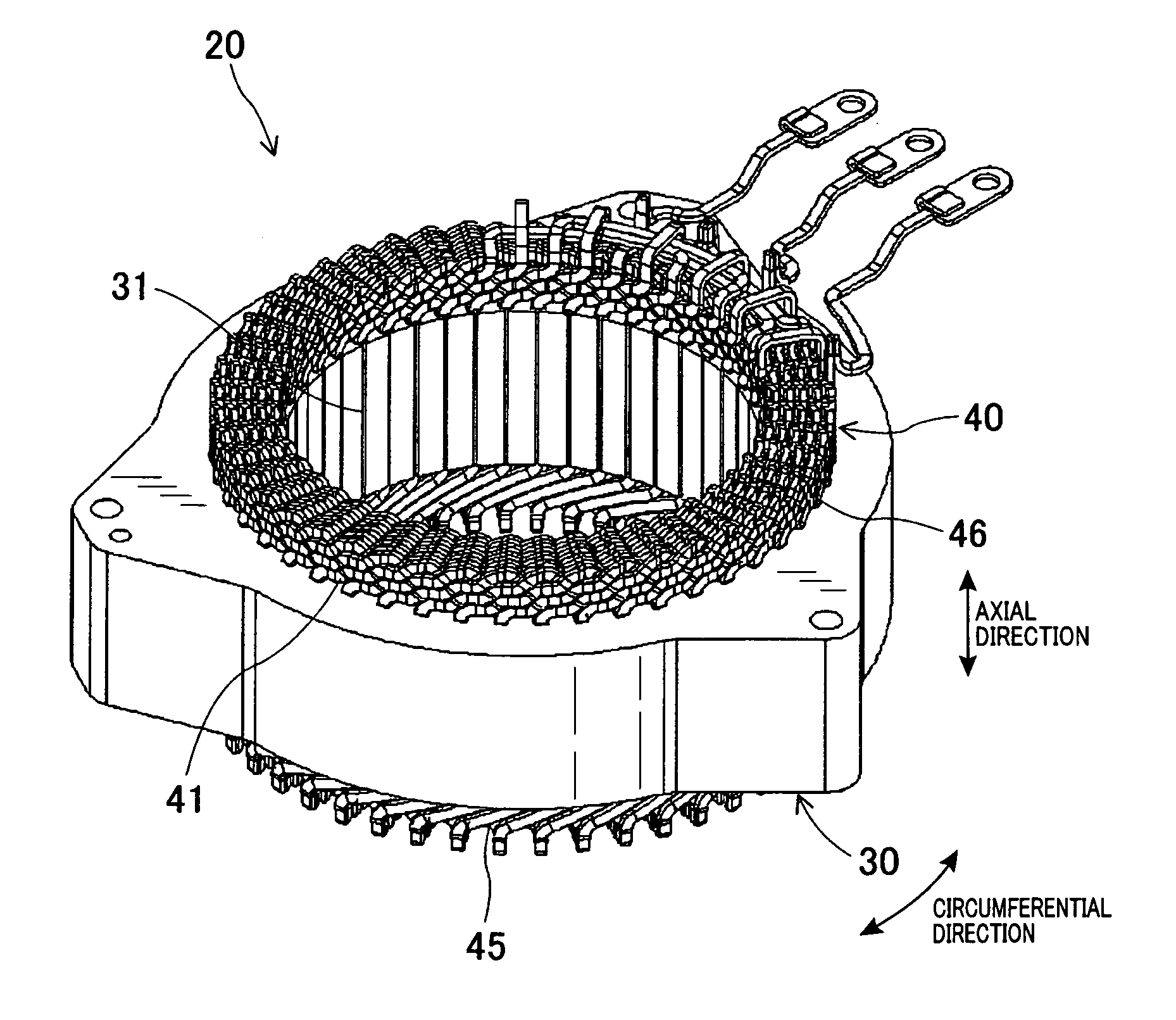
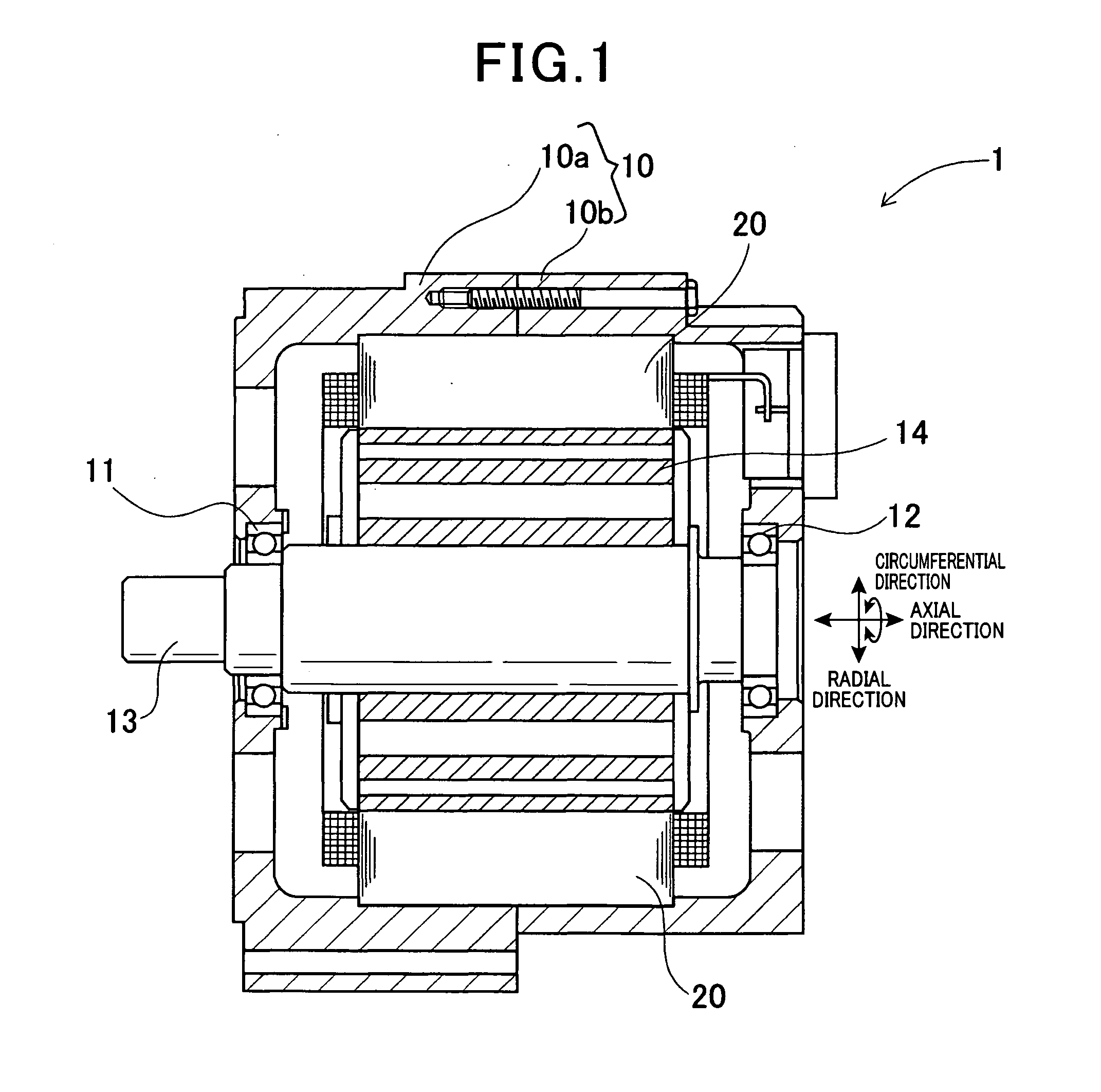
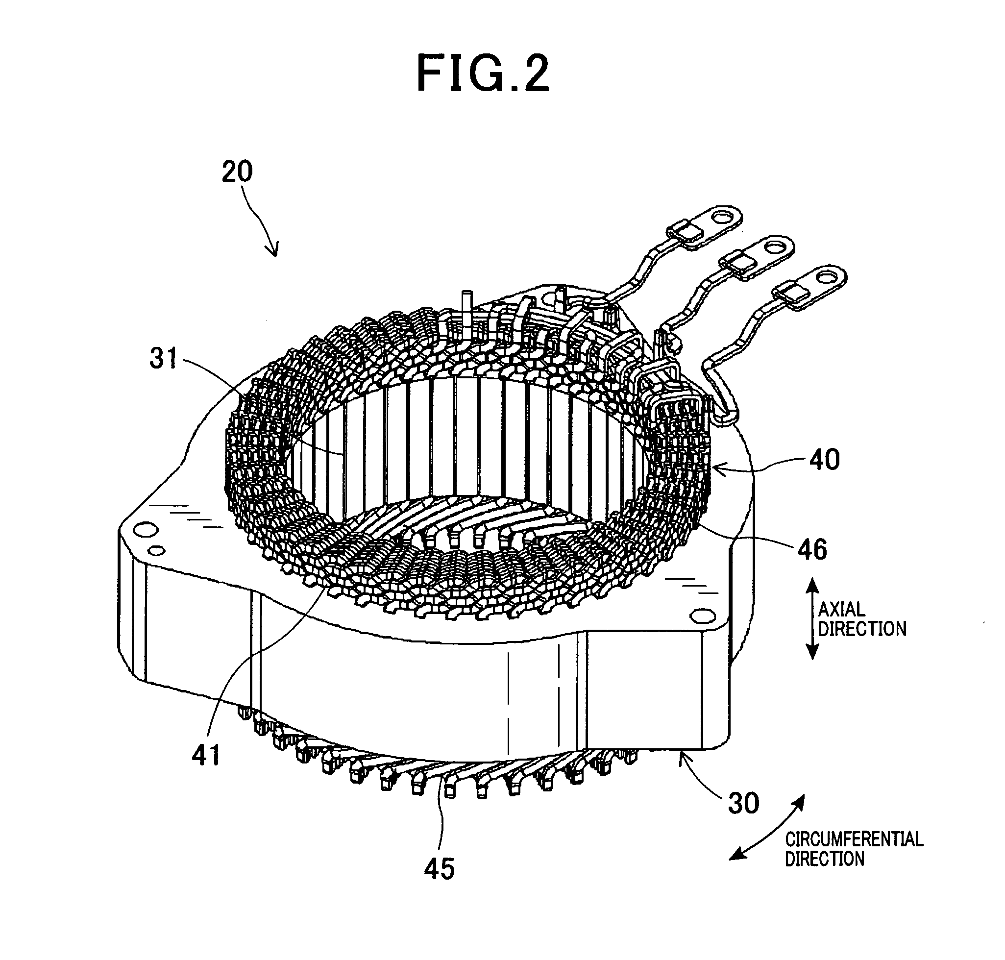
[0050]FIG. 1 is an axial-direction cross-sectional view schematically showing a configuration of a rotary electrical machine according to the embodiment. FIG. 2 is a perspective view of a stator according to the embodiment, viewed from a segment conductor insertion side. FIG. 3 is a perspective view of the stator according to the embodiment, viewed from a segment conductor welding side. FIG. 4 is a partial planar view of main sections of a stator core according to the embodiment.

[0051]A rotary electrical machine 1 according to the present embodiment includes a housing 10, a rotor 14, and a stator 20. The housing 10 is composed of a pair of bottomed,...


PUM


Abstract

A stator includes a ring-shaped stator core and a stator winding. The stator core has a plurality of slots arranged in a circumferential direction. The stator winding has a plurality of phase windings. Each phase winding is composed of a plurality of segment conductors 41 disposed such as to be inserted into the slots and connected in series. The segment conductor is divided into two. The phase winding is configured by two divided phase windings connected to each other in parallel. The divided phase windings are respectively configured by a plurality of segment conductors respectively connected in series such that the two divided segment conductors are in parallel with each other.

Description

CROSS-REFERENCE TO RELATED APPLICATION[0001]This application is based on and claims the benefit of priority from earlier Japanese Patent Application No. 2010-276671 filed Dec. 13, 2010, the description of which is incorporated herein by reference.BACKGROUND OF THE INVENTION[0002]1. Field of the Invention[0003]The present invention relates to a stator for a rotary electrical machine that is, for example, mounted in a vehicle.[0004]2. Description of the Related Art[0005]As a stator for a rotary electrical machine, for example, as disclosed in U.S. Pat. No. 4,186,317, a stator is known that includes a ring-shaped stator core and a stator winding. The stator core has a plurality of slots arranged in a circumferential direction. The stator winding has a plurality of phase windings composed of a plurality of segment conductors that are disposed such as to be inserted into the slots and connected in series.[0006]As shown in a connection diagram in FIG. 23B, each phase winding 143 configuri...

Claims


Application Information

Patent Timeline
IPC IPC(8): H02K3/12H02K3/28
CPCH02K3/12H02K3/04H02K3/50H02K3/28
Inventor SEGUCHI, MASAHIROITOU, YUUICHIROU
Owner DENSO CORP
Why Eureka
Try Eureka