Light emitting diode driver havng cascode structure

a technology of cascode structure and driver, which is applied in the direction of lighting apparatus, electroluminescent light sources, light sources, etc., can solve the problems of reduced system reliability and high manufacturing cos

Inactive Publication Date: 2012-06-14
JEONG JAE HONG
View PDF8 Cites 16 Cited by
  • Summary
  • Abstract
  • Description
  • Claims
  • Application Information

AI Technical Summary

Benefits of technology

[0005]In one embodiment of the present disclosure, a method for driving light emitting diodes (LEDs) includes: providing a string of LEDs divided into groups, the groups being electrically connected to each other in series; providing a power source electrically connected to the string of LEDs; coupling each of the groups to a ground through a separate current regulating circuit, the separate current regulating circuit including a cascode structure having first and second transistors; and increasing an input voltage from the power source to turn on the groups in a downstream sequence.

Problems solved by technology

These converters, which employ an inductor or transformer, capacitor, and / or other components, are large in size and have short life, which results in an undesirable form factor in lamp design, high manufacturing cost, and reduction in system reliability.

Method used


Image

  • Light emitting diode driver havng cascode structure
  • Light emitting diode driver havng cascode structure
  • Light emitting diode driver havng cascode structure

Examples


Embodiment Construction

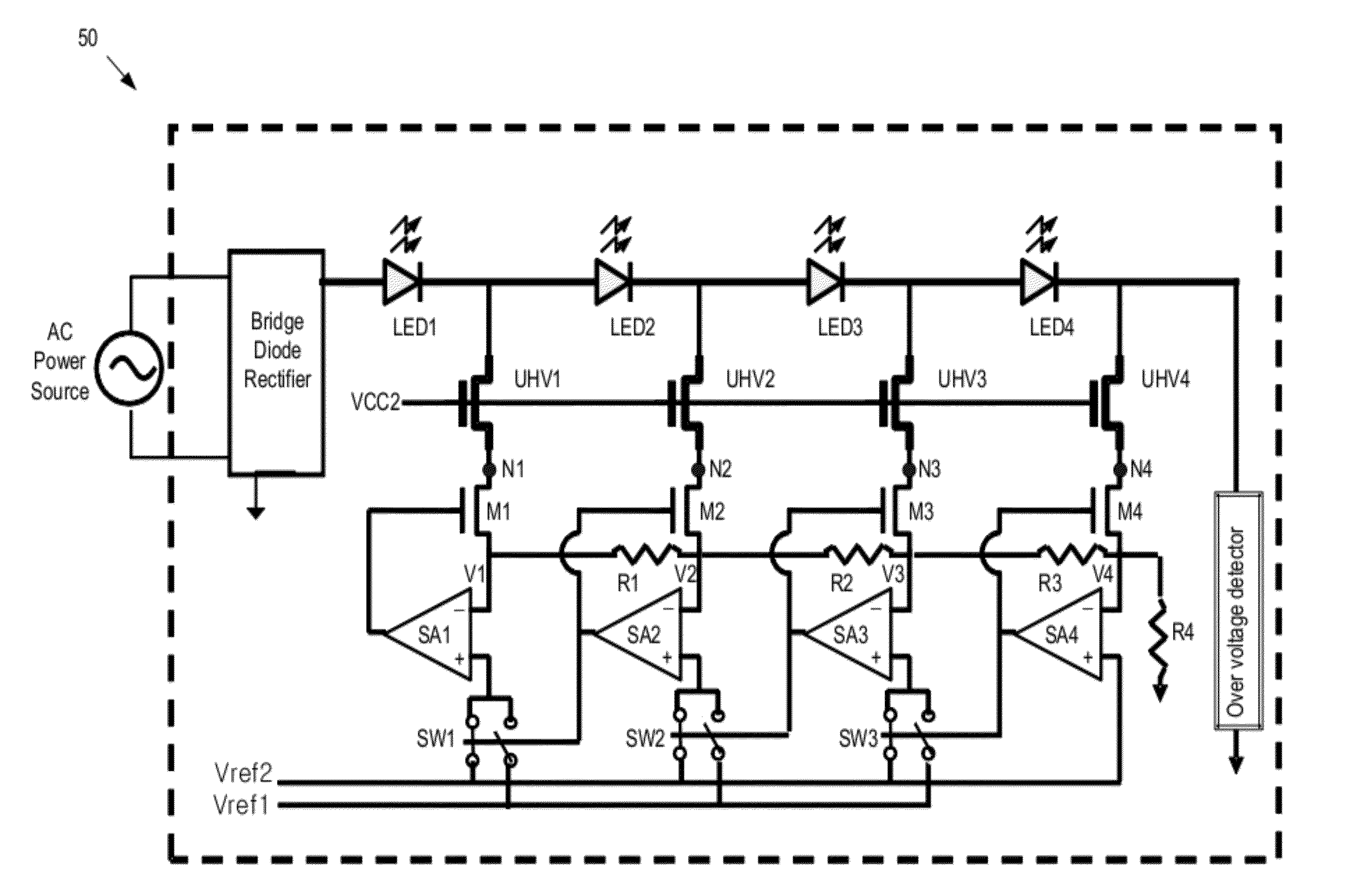
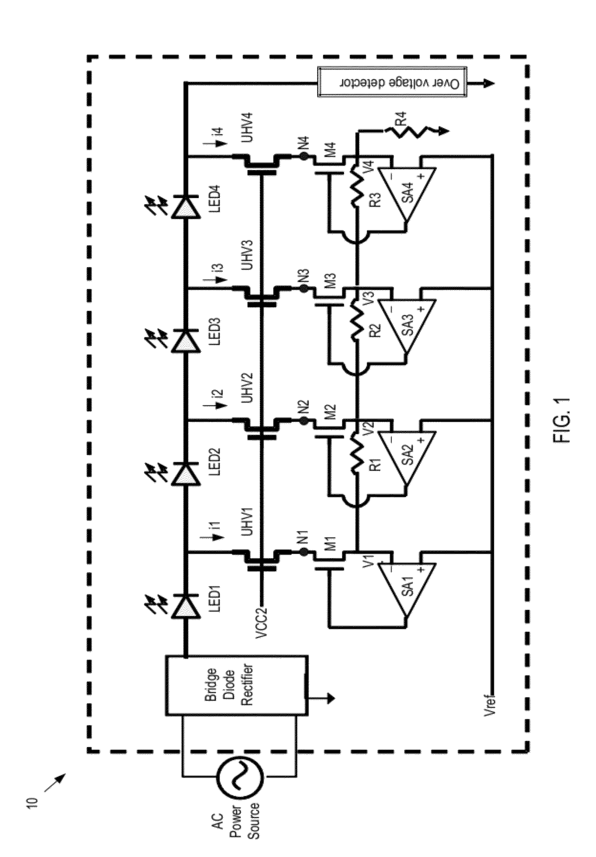
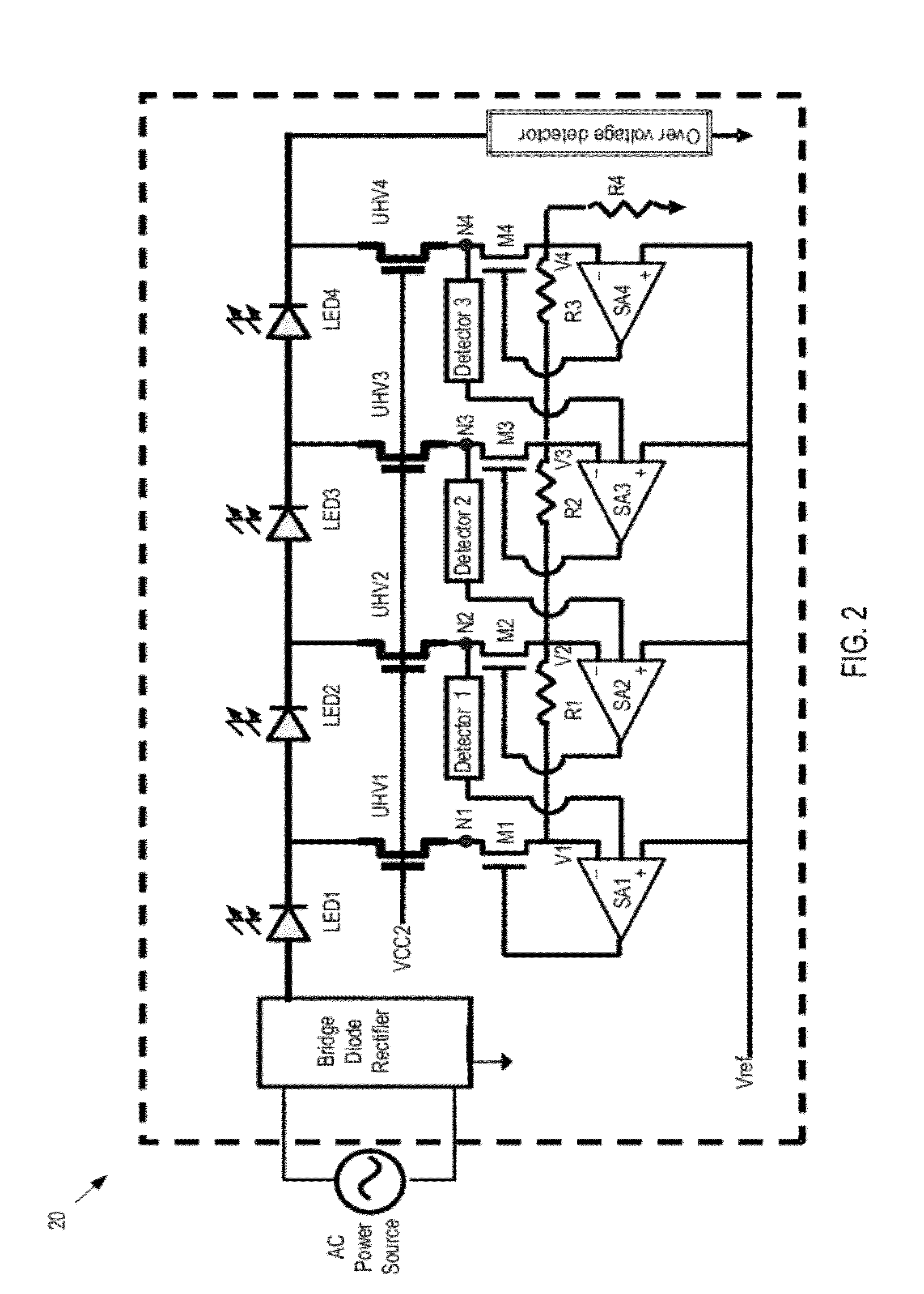
[0018]Referring now to FIG. 1, there is shown a schematic diagram of an LED driver circuit (or, shortly driver) 10 in accordance with one embodiment of the present invention. As depicted, the driver 10 is powered by a power source such as an alternative current (AC) power source. The electrical current from the AC power source is rectified by a rectifier circuit. The rectifier circuit can be any suitable rectifier circuit, such as bridge diode rectifier, capable of rectifying the alternating power from the AC power source. The rectified voltage Vrect is then applied to a string of light emitting diodes (LEDs). If desirable, the AC power source and the rectifier may be replaced by a direct current (DC) power source.

[0019]The LEDs as used herein is the general term for many different kinds of light emitting diodes, such as traditional LED, super-bright LED, high brightness LED, organic LED, etc. The drivers of the present invention are applicable to all kinds of LED.

[0020]As depicted ...


PUM


Abstract

A driver circuit for driving light emitting diodes (LEDs). The driver circuit includes: a string of LEDs divided into n groups, the n groups of LEDs being electrically connected to each other in series, a downstream end of group m−1 being electrically connected to the upstream end of group m, where m is a positive number equal to or less than n. The driver circuit also includes a power source coupled to an upstream end of group 1 and operative to provide an input voltage and a plurality of current regulating circuits, each of the current regulating circuits being coupled to the downstream end of a corresponding group at one end and coupled to a ground at the other end and including a sensor amplifier and a cascode having first and second transistors.

Description

CROSS REFERENCES[0001]This application claims the benefit of U.S. Provisional Applications No. 61 / 422,128, filed on Dec. 11, 2010, entitled “Light emitting diode driver using turn-on voltage of light emitting diode,” and relates copending U.S. application Ser. No. ______, filed on Sep. 26, 2011, entitled “Light emitting diode driver,” and U.S. application Ser. No. ______, filed on Sep. 26, 2011, entitled “Light emitting diode driver having phase control mechanism,” which are hereby incorporated by reference in their entirety.BACKGROUND OF THE INVENTION[0002]The present invention relates to a light emitting diode (LED) driver, and more particularly, to a circuit for driving a string of light emitting diode (LEDs).[0003]Due to the concept of low energy consumption, LED lamps are prevailing and considered a practice for lighting in the era of energy shortage. Typically, an LED lamp includes a string of LEDs to provide the needed light output. The string of LEDs can be arranged either i...

Claims


Application Information

Patent Timeline
Patent Type & Authority Applications(United States)
IPC IPC(8): H05B37/02H05B44/00
CPCH05B33/083H05B33/0815H05B33/089H05B45/48H05B45/50H05B45/37H05B47/24
Inventor JEONG, JAE HONG
Owner JEONG JAE HONG
Why Eureka
Try Eureka