
Rescue circuit of display panel and rescue method thereof

a display panel and rescue circuit technology, applied in static indicating devices, instruments, non-linear optics, etc., can solve the problems of signal line b>14/b> getting broken and thus open, and achieve the effect of reducing the rc delay of a posterior portion

Active Publication Date: 2012-06-14
TCL CHINA STAR OPTOELECTRONICS TECH CO LTD
View PDF2 Cites 20 Cited by
  • Summary
  • Abstract
  • Description
  • Claims
  • Application Information

AI Technical Summary

Benefits of technology

The present invention provides a rescue circuit and method for display panels that can overcome problems such as weak line and broken signal lines. The rescue circuit includes an amplifier, conductive lines, and an isolation layer. The conductive lines are connected to the amplifier to reduce signal delay and deterioration of the display signal. The method involves welding and cutting the broken signal lines to alleviate the weak line problem. Overall, the invention improves the reliability and performance of display panels.

Problems solved by technology

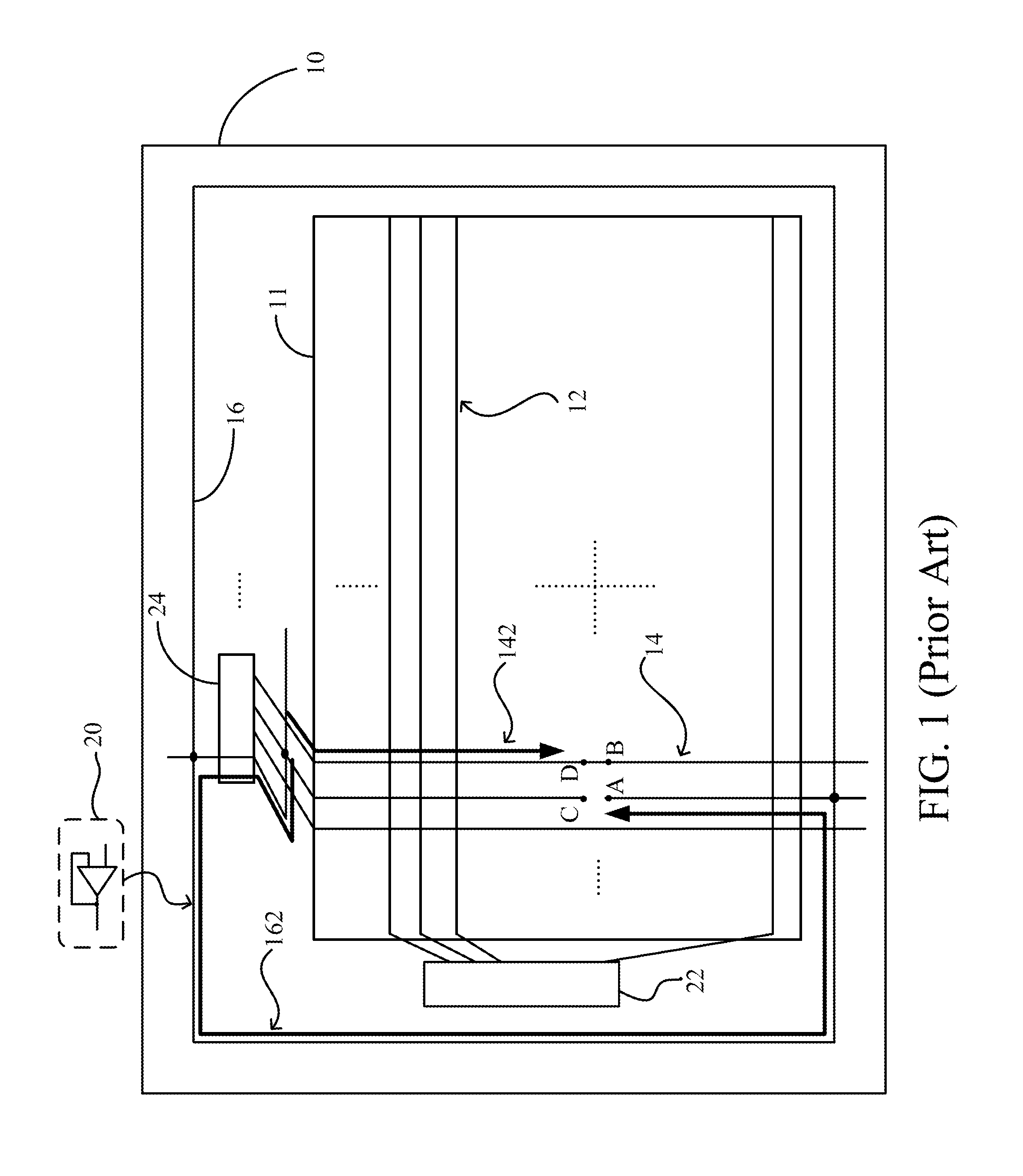
Consequently, a signal line 14 may get broken and thus open in the manufacturing process due to a foreign object (such as dust).
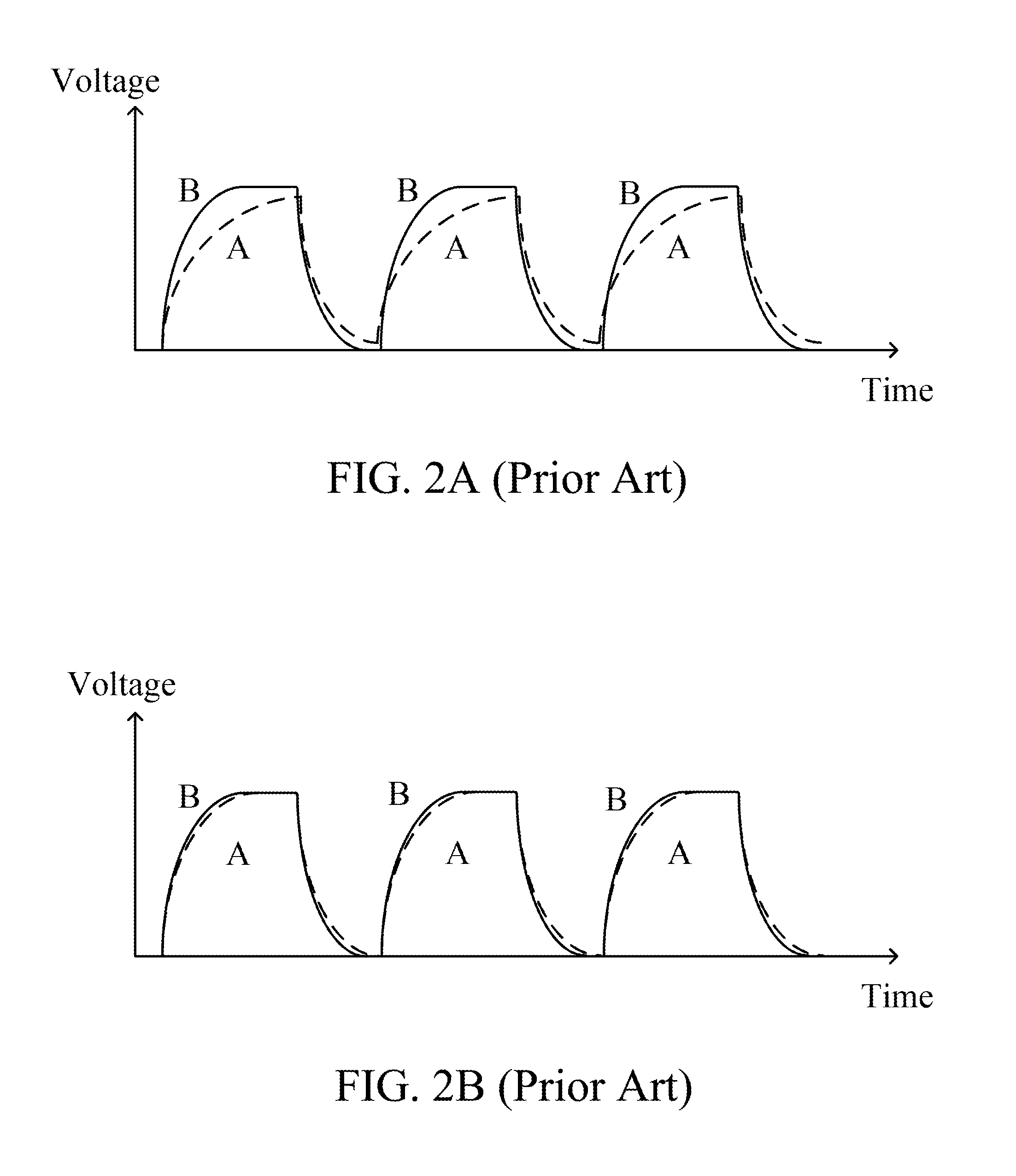
As a consequence, distortion of the display signal at point A is severer than at point B. However, a significant difference of the display signals may lead to the situation that the charging ratio at point A is much smaller than that at point, thus causing a weak line phenomenon around point A.

Method used


Image

  • Rescue circuit of display panel and rescue method thereof
  • Rescue circuit of display panel and rescue method thereof
  • Rescue circuit of display panel and rescue method thereof

Examples


Embodiment Construction

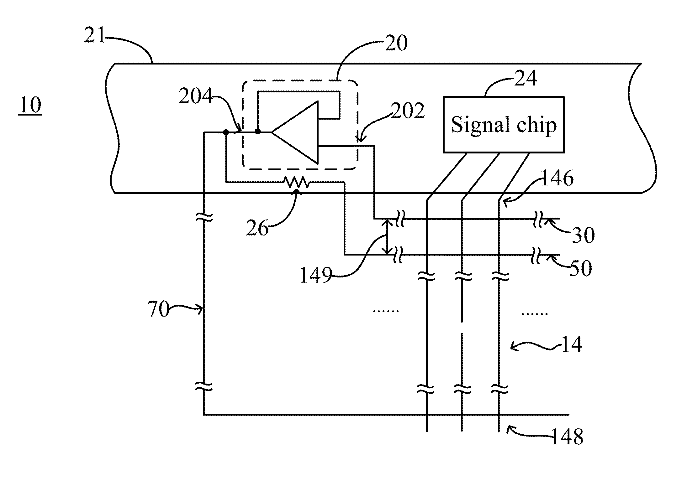
[0025]Reference is now made to FIG. 4. FIG. 4 is a schematic view illustrating a rescue circuit of display panel according to a preferred embodiment of the present invention. In the preferred embodiment, the display panel comprises a substrate 10, and a plurality of scan lines (not shown) and a plurality of signal lines 14 are provided on the substrate 10 with the plurality of scan lines arranged to be parallel to each other and intersecting the plurality of signal lines 14. The scan lines and the signal lines 14 form a plurality of pixel areas therebetween, each being controlled by a thin film transistor (TFT) (not shown) for pixel refreshing.

[0026]Each of the signal lines 14 has a signal input terminal 146 and a signal distal end 148 for transmission of a display signal. Specifically, the substrate 10 comprises a plurality of signal chips 24 arranged thereon. For clear illustration, only one signal chip 24 is shown in the drawings. The signal chip 24 functions to provide the displ...


PUM

PropertyMeasurementUnit
conductiveaaaaaaaaaa
distanceaaaaaaaaaa
areaaaaaaaaaaa

Abstract

The present invention discloses a rescue circuit of display panel and a rescue method thereof. The rescue circuit includes an amplifier, a first conductive line, a second conductive line, and a third conductive line. The amplifier has an input end and an output end. The first conductive line and the second conductive line intersect and are isolated from signal input terminals of the plurality of signal lines. The first conductive line is electrically connected to the input end and the second conductive line is electrically connected through an electrical resistor to the output end. The third conductive line intersects and is isolated from signal distal ends of the signal lines and is electrically connected to the output end. The rescue method includes performing a welding operation and performing a cutting operation. With such a rescue, a broken signal line may effectively overcome the problem of weak line with the electrical resistor connected to the second conductive line.

Description

BACKGROUND OF THE INVENTION[0001]1. Field of the Invention[0002]The present invention generally relates to a rescue circuit of display panel and a rescue method thereof, and in particular to a rescue circuit of display panel and a rescue method thereof that improve resistive-capacitive (RC) delay occurring in a signal line.[0003]2. The Related Arts[0004]FIG. 1 is a schematic view illustrating a conventional way of rescuing a signal line of a liquid crystal display panel. As shown in FIG. 1, the liquid crystal display panel comprises a substrate 10, and a plurality of scan lines 12 and a plurality of signal lines 14 are provided on the substrate 10 with the plurality of scan lines 12 arranged to be parallel to each other and intersecting the plurality of signal lines 14. The scan lines 12 and the signal lines 14 form a plurality of pixel areas therebetween, each being controlled by a thin film transistor (TFT) (not shown) for pixel refreshing. Further, the substrate 10 comprises a sc...

Claims


Application Information

Patent Timeline
Patent Type & Authority Applications(United States)
IPC IPC(8): G02F1/1345
CPCG02F1/136259G09G3/20G09G2330/08G09G2300/0426G09G2320/0223G02F2001/136263G02F1/136263
Inventor CHEN, CHENGHUNGHE, CHENGMING
Owner TCL CHINA STAR OPTOELECTRONICS TECH CO LTD
Learn More