End mill

a technology of end mills and end plates, which is applied in the direction of metal-working equipment, milling equipment, metal-working apparatus, etc., can solve the problems of reducing cutting edge sharpness, affecting cutting performance, and affecting cutting edge sharpness, so as to improve fracture resistance and reduce the effect of bending and bending resistance and large cutting resistan

Active Publication Date: 2012-06-14
MITSUBISHI MATERIALS CORP
View PDF29 Cites 6 Cited by
  • Summary
  • Abstract
  • Description
  • Claims
  • Application Information

AI Technical Summary

Benefits of technology

[0008]The present invention was made in view of such a problem and the object thereof is to provide an end mill capable of improving the fracture resistance of each cutting edge to prolong its tool life and to prevent burrs from being generated in a workpiece so that good cutting can be performed.
[0010]In an end mill having the above construction, where the honing width of the cutting edge is large an improved fracture resistance is provided to endure a large cutting resistance; and where the honing width of the cutting edge is small, sharpness of the cutting edge is maintained for excellent cutting performance. Accordingly, the end mill, in which the honing width of the peripheral cutting edge is variable in the direction of the axis according to the cutting conditions, shows good performance. For example, the honing width of the peripheral cutting edge may be increased in the place where fracture tends to occur, and decreased in the other places. Such variable honing width enables the cutting edge to maintain good cutting performance together with a prolonged tool life, and to prevent the generation of burrs.
[0012]When feeding the end mill in a direction intersecting with the axis in order to cut a workpiece, a part of each peripheral cutting edge, which is at the periphery of the top of the end mill and is located on the front side in the end mill rotating direction, initially touches the workpiece and bites into it. Each peripheral cutting edge is helical, and is provided with a flute. Therefore, this part tends to be fractured due to the biting impact. However, the end mill of the present invention has a construction in which the honing width of each peripheral cutting edge is greatest at the part on the front side in the end mill rotating direction, and becomes gradually smaller toward the rear side in the end mill rotating direction. This construction improves the fracture resistance at the place where fracture is most likely to occur; and while other parts of each cutting edge are able to maintain its cutting performance. Therefore, the tool life of each cutting edge can be prolonged, and also the generation of burrs can be prevented.
[0013]Additionally, in an end mill according to the present invention, the honing width of the peripheral cutting edge becomes gradually greater from the front side in the end mill rotating direction toward the rear side in the end mill rotating direction.
[0014]For example, a workpiece with a surface harder than its other portions may be machined by using a general helical flute type end mill in which each flute is twisted helically in the end mill rotating direction from the top side toward the rear end side. In such a case, since each of the cutting edges nearer to the rear end side of the end mill cuts the surface of the workpiece; the rear end side of the cutting edge tends to be fractured. The honing of the peripheral cutting edge is made to have a construction in which the honing width becomes gradually greater from the front side in the end mill rotating direction toward the rear side in the end mill rotating direction. In other words, the honing width gradually increases from the front side of the end mill toward the rear end side thereof. Such a construction can improve the fracture resistance at the rear end side, where each peripheral cutting edge cuts the surface of such workpiece, will be the top side of each peripheral cutting edge can maintain its cutting performance. Therefore, even if a workpiece with a hard surface is machined, it is possible to prolong the tool life of the cutting edges.
[0015]According to an end mill related to the invention, the honing width of each peripheral cutting edge is variable in the direction of the axis. This construction can improve the fracture resistance of each peripheral cutting edge, and also can prolong the tool life. Further, this construction maintains the cutting performance of the cutting edge, and prevents the generation of burrs in a workpiece. Therefore, a cutting operation can be performed in a good condition.

Problems solved by technology

However, if the cutting edges are excessively sharp for cutting a workpiece, cutting force may concentrate in the cutting edges, and then fracture may occur thereon.
If the cutting edges with such fracture continue cutting; a problem arises in which the cutting performance becomes remarkably poor.
However, the honing also makes the sharpness of the cutting edges decrease, and consequently its cutting performance becomes poor.
Also, burrs generated in a workpiece cause a poor finished surface.
Since an extra process of removing these burrs is required, the possibility arises that machining cost will increase.

Method used


Image

  • End mill
  • End mill
  • End mill

Examples


Embodiment Construction

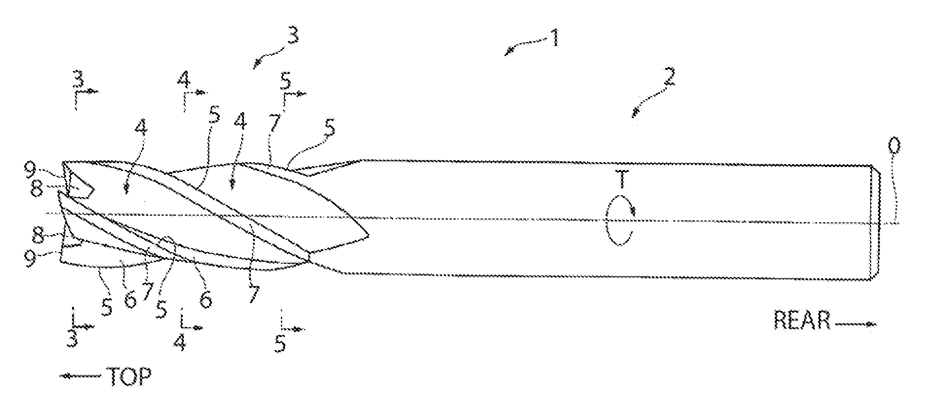
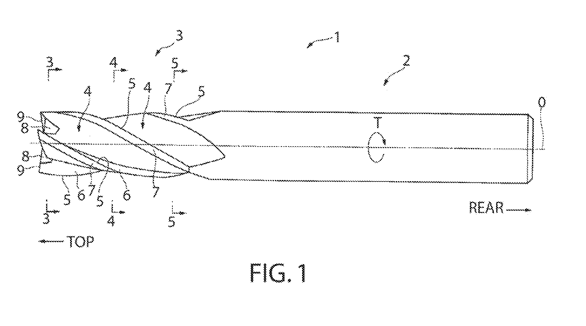
[0022]In a preferred embodiment of the present invention, an end mill has an end mill body 1, which is in a cylindrical shape substantially and rotates on an axis O.

[0023]A rear end (rightmost in FIG. 1) of the end mill body 1 comprisesa shank portion 2 by which a spindle end of a machine tool, etc. can grip the end mill body 1.

[0024]A top portion (leftmost in FIG. 1) of the end mill body 1 comprisesa cutting edge potion 3.

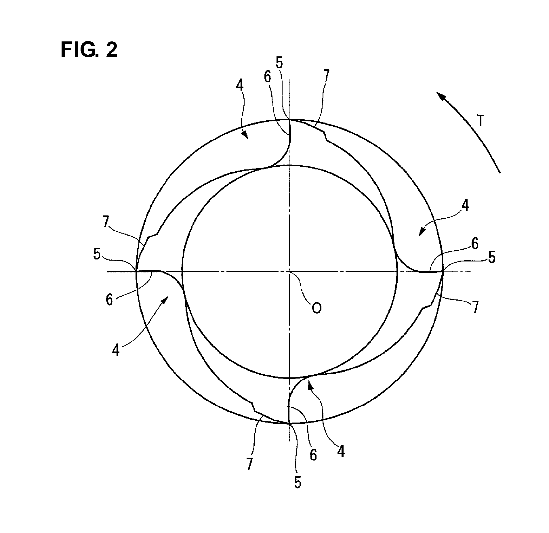
[0025]In a periphery of the cutting edge portion 3, multiple (four as illustrated in the present embodiment) flutes 4 in a helical shape around the axis O with a constant helix angle, which is an angle rearward in the end mill rotating direction T, are formed from the top side of the end mill body 1 toward the rear end side at intervals of a radial constant. Intersecting ridge portions are formed between twall surfaces of the flutes 4 facing to the front side in the end mill rotating direction T and peripheral surfaces connected continuously with rears of the wall...


PUM


Abstract

An end mill including multiple spiral flutes in a helical shape around an axis that are formed in a periphery of the top portion of an end mill body which rotates on the axis. Cutting edges are formed at peripheral side ridge portions of wall surfaces of the flutes facing a front side in an end mill rotating direction. Honing is applied along each peripheral cutting edge such that the cutting edge has a variable honing width in the direction of the axis.

Description

CROSS-REFERENCE TO RELATED APPLICATIONS[0001]This is a U.S. national phase application under 35 U.S.C. §371 of International Patent Application No. PCT / JP2008 / 064438 filed Aug. 12, 2008, which claims the benefit of Japanese Application No. 2007-214698 filed Aug. 21, 2007, each of which is incorporated by reference herein its entirety. The International Application was published in Japanese on Feb. 26, 2009 as International Publication No. WO / 2009 / 025197 under PCT Article 21(2).FIELD OF THE INVENTION[0002]The present invention relates to an end mill including multiple flutes formed on a periphery of a top portion, of an end mill body which rotates on an axis, and peripheral cutting edges formed along peripheral side ridge portions of the wall surfaces of the flutes facing toward the end mill rotating direction.BACKGROUND OF THE INVENTION[0003]Conventionally, for example, an end mill used for die cutting, etc. includes an end mill body made of a hard material, such as cemented carbide...

Claims


Application Information

Patent Timeline
Patent Type & Authority Applications(United States)
IPC IPC(8): B23C5/10
CPCY10T407/1962Y10T407/1948B23C5/10B24B3/06
Inventor MIKI, TAKASHITAKAGI, YUJI
Owner MITSUBISHI MATERIALS CORP
Why Eureka
Try Eureka