Thermogenic Augmentation System

a technology of augmentation system and thermal insulation, which is applied in ventilation system, lighting and heating apparatus, heating type, etc., can solve the problems of only a small fraction of the total electrical power produced worldwide, high stress on the electrical power infrastructure, and increase harmful emissions of carbon dioxide and other greenhouse gases, so as to reduce electrical or other power consumption/generation and the associated carbon emissions

Active Publication Date: 2012-06-14
RODERICK DAVID
View PDF3 Cites 50 Cited by
  • Summary
  • Abstract
  • Description
  • Claims
  • Application Information

AI Technical Summary

Benefits of technology

[0009]It is a further object of the invention to reduce electrical or

Problems solved by technology

In warm sunny climates, air conditioning or other mechanical means for cooling dwellings, office buildings and any other structure that needs to be maintained below a critical temperature consumes significant energy, places high stress on the electrical power infrastructure and increases harmful emissions of carbon dioxide and other greenhouse gases, depending on the sources of power.
While there are alternative

Method used


Image

  • Thermogenic Augmentation System
  • Thermogenic Augmentation System
  • Thermogenic Augmentation System

Examples


Embodiment Construction

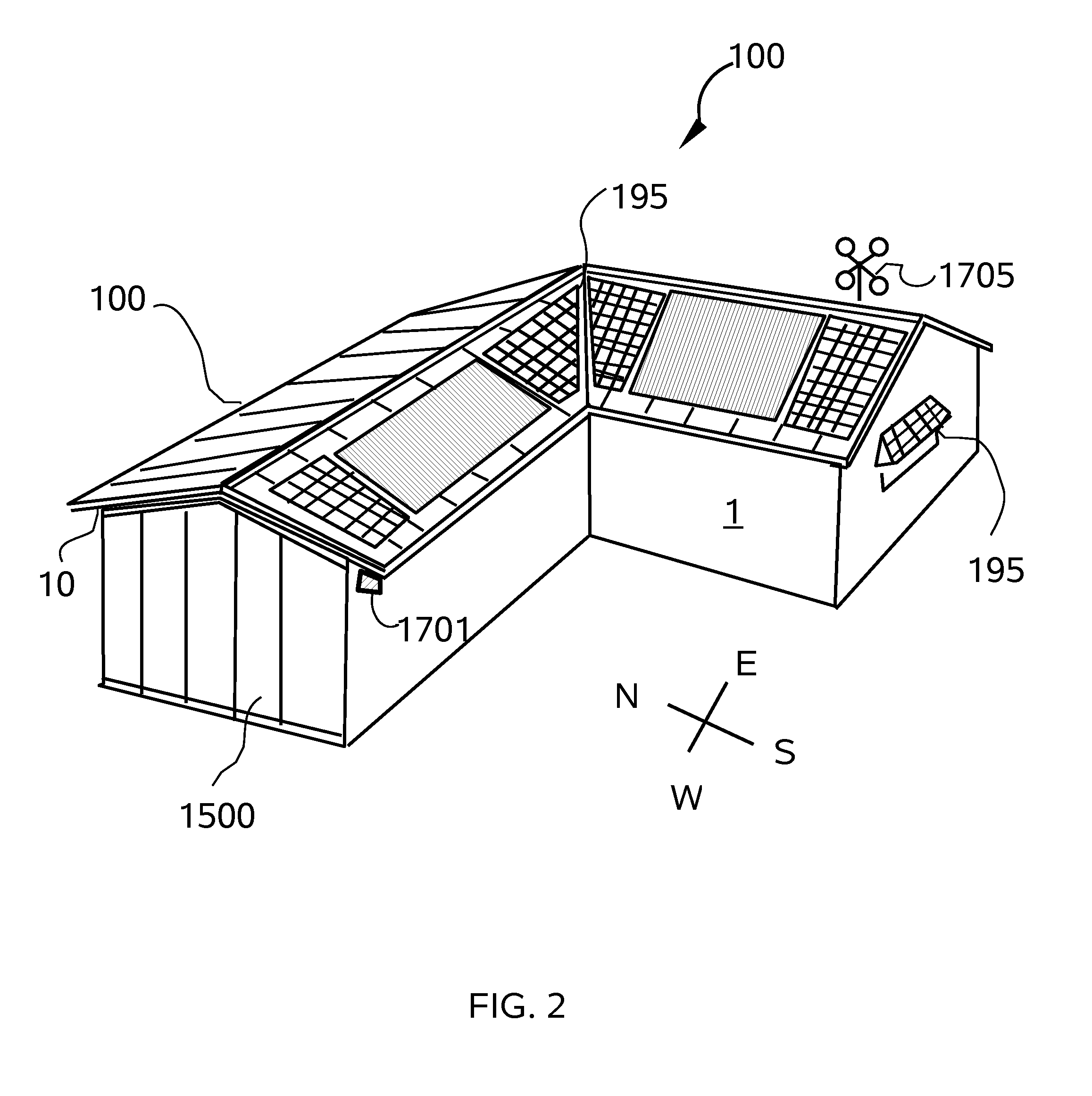
[0060]Referring to FIGS. 1 through 33, wherein like reference numerals refer to like components in the various views, there is illustrated therein a new thermogenic augmentation system, generally denominated 100 herein.

[0061]In accordance with the present invention the active solar heat shield and roof system 100 is deployed on a pitched or shed roof, but can alternatively be deployed on any structure or enclosure with a sealed roof surface or a vertical wall, as well as smaller structures, such as utility cabinets, storage sheds and shipping containers, and outdoor metal or plastic toilets.

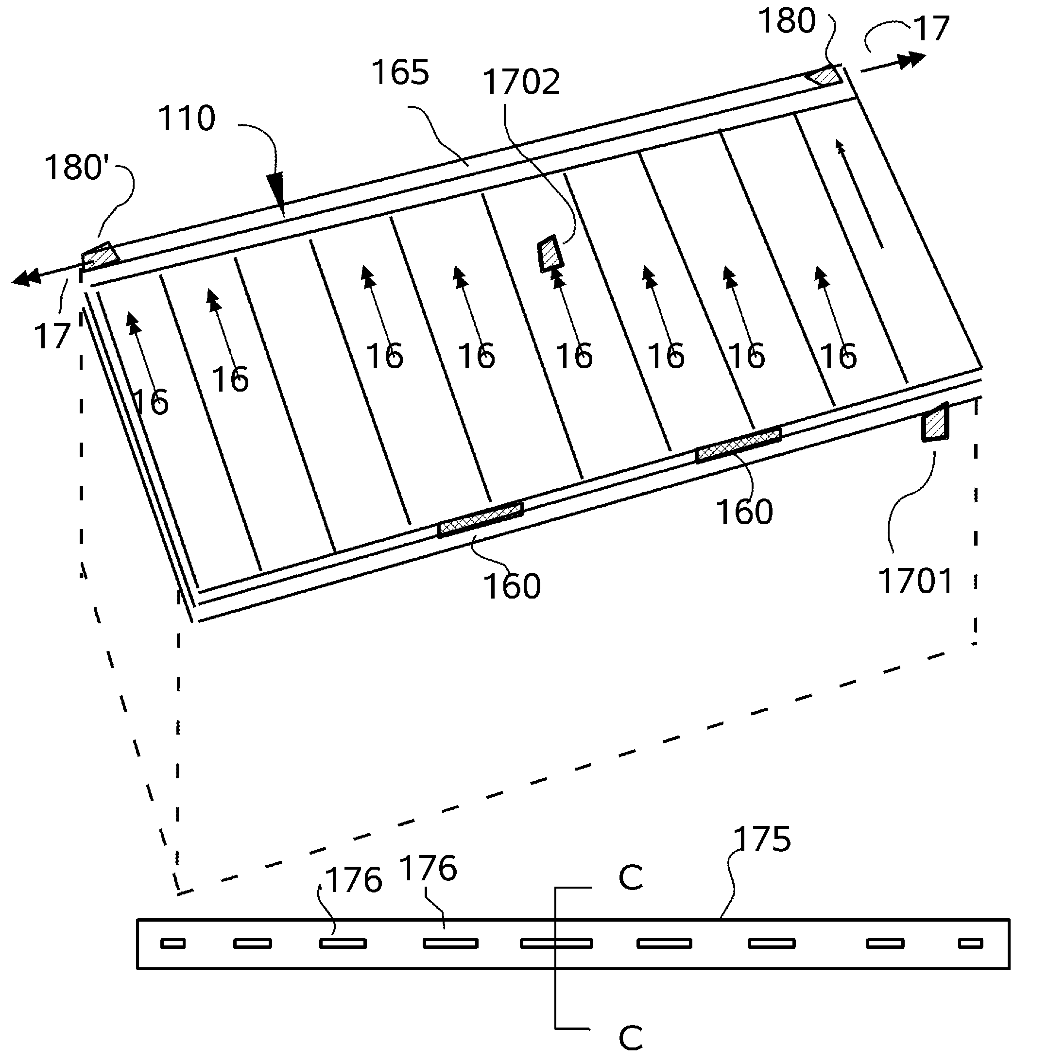
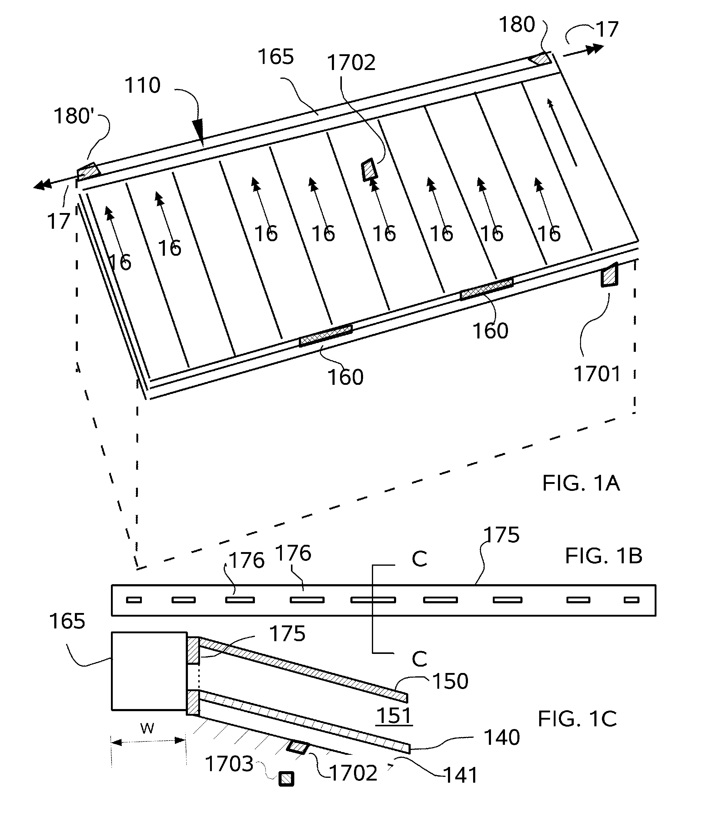
[0062]FIGS. 1-4 illustrate a first embodiment in which the passive solar heat shield 100 is deployed on a pitched roof 1; and a variant thereof 1500 is deployed on a west facing (but optionally any wall) vertical wall surface. The active solar heat shield and roof system 100 is deployed on a building structure 1 having a roof or wall frame 10 and generally comprises a radiant barrier cover or lay...


PUM


Abstract

A dual air cavity roof has a continuous upper cavity which is cooled by fans, while the lower cavity is generally sealed. Preferably the cavities are separated by a radiant barrier. The fans are preferably powered by one or more photovoltaic cells that are also disposed on the roof. The roof can be pre-cooled with cooler night air and fans only activated when necessary to remove heat from the solar load on the upper cavity. When it is desirable to remove heat, the fan speed is optimized in each zone of the roof to enhance the natural convective flow to the optimum level. A radiant barrier can also cover the roof substrate, which is optionally an existing roof that is in need of repair. The roof structure is preferably assembled in parallel modules using insulating support brackets that support the outer surface and the barrier that separates the upper and lower cavity.

Description

CROSS REFERENCE TO RELATED APPLICATIONS[0001]The present application claims the benefit of priority to the U.S. Provisional Patent Application of the same title that was filed on Jul. 15, 2010, having application Ser. No. 61 / 364,564, and is incorporated herein by reference.[0002]The present application is also a Continuation-in-Part of and claims the benefit of priority to the U.S. Non-Provisional Patent Application for a “Solar Power Augmented Heat Shield Systems” that was filed on Jul. 14, 2010, having application Ser. No. 12 / 835,979, and is incorporated herein by reference, which in turn claims the benefit of priority to the U.S. Provisional Patent Application for a “Solar Power Augmented Heat Shield Systems” that was filed on Jul. 19, 2009, having application Ser. No. 61 / 226,722, and is incorporated herein by reference.BACKGROUND OF INVENTION[0003]The present invention relates to a method of cooling and heating buildings and structures that does not require direct external energ...

Claims


Application Information

Patent Timeline
IPC IPC(8): F24F7/007F24F7/003
CPCF24F11/0001F24F11/0012F24F2007/004F24F2011/0039E04D13/17F24F2011/0006F24F11/30F24F2110/10F24F2110/32F24F11/76F24F11/46F24F11/63F24F7/003
Inventor RODERICK, DAVIDBEIGLER, MYRON
Owner RODERICK DAVID
Why Eureka
Try Eureka