
Ultrasound probe

a technology of ultrasound probes and probes, applied in the field of ultrasound probes, can solve the problems that the safety of operators manipulating ultrasound probes for ultrasound diagnoses (doctors making ultrasound diagnoses) is not taken into account at all, and achieves the effect of reducing heat generation and ensuring the safety of the operator

Active Publication Date: 2012-06-14
FUJIFILM CORP
View PDF6 Cites 26 Cited by
  • Summary
  • Abstract
  • Description
  • Claims
  • Application Information

AI Technical Summary

Benefits of technology

The present invention provides an ultrasound probe that includes an ultrasonic wave-generating unit, an integrated circuit board, and a battery for use as a power supply for driving the ultrasound probe. The probe has a case with a grip portion and functional units that include at least an ultrasonic wave-generating unit, integrated circuit board, and battery. The functional units have thermally conductive members for heat release independently of each other, and at least two of the functional units are insulated from each other. The battery is disposed at the position corresponding to the grip portion for an operator to hold and is set in the case. The inventive ultrasound probe can suppress heat generation in the grip portion while ensuring the safety of the operator from heat.

Problems solved by technology

Conventional probes give weight to the safety of subjects from heat but the safety of operators manipulating probes for ultrasound diagnoses (doctors making ultrasound diagnoses) is not taken into account at all.

Method used


Image

  • Ultrasound probe
  • Ultrasound probe
  • Ultrasound probe

Examples


Embodiment Construction

[0029]Next, the ultrasound probe of the invention is described in detail by referring to the preferred embodiments shown in the accompanying drawings.

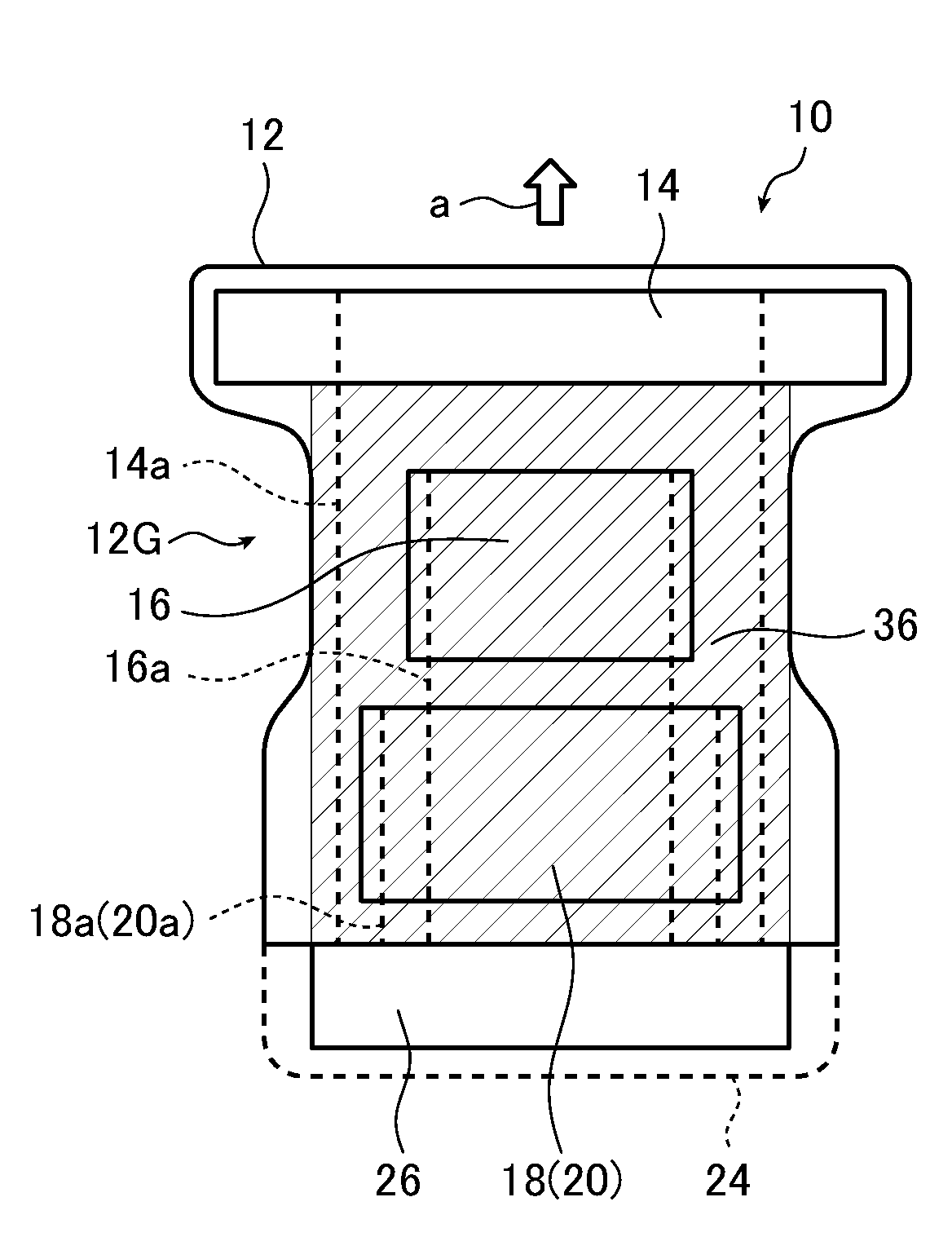
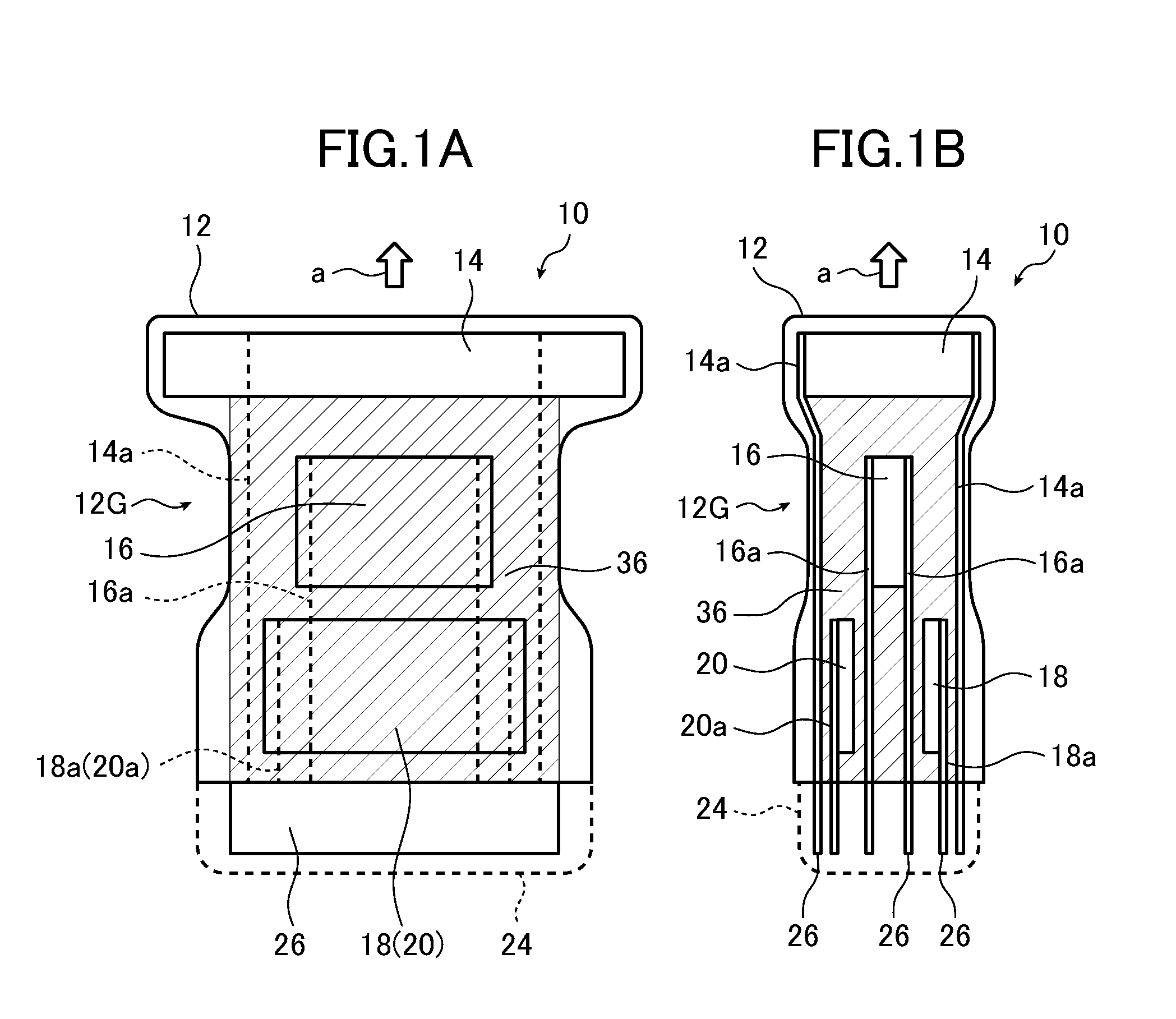
[0030]FIGS. 1A and 1B conceptually show the configuration of an ultrasound probe of the invention.

[0031]FIG. 1A is a side view and FIG. 1B is a plan view. Ultrasound transducers 46 of an ultrasonic wave-generating unit 14 to be described later are disposed transversely in FIG. 1A and in a direction perpendicular to the plane of paper in FIG. 1B.

[0032]An ultrasound probe 10 (hereinafter referred to as “probe 10”) shown in FIGS. 1A and 1B is a wireless communication type ultrasound probe which transmits ultrasonic waves to a subject, receives ultrasonic echoes from the subject, converts the received ultrasonic echoes into electric signals, processes the electric signals and transmits the processed electric signals as ultrasound image signals to a diagnostic apparatus body 42 to be described later through wireless communication.

[0033]The ...


PUM


Abstract

An ultrasound probe which transmits ultrasonic waves to a subject, receives ultrasonic echoes generated by reflection of the ultrasonic waves on the subject and outputs ultrasound image signals includes a case having a grip portion set therein and functional units disposed in the case. The functional units include an ultrasonic wave-generating unit, at least one integrated circuit board and a battery. The battery disposed in the case at a position corresponding to the grip portion ensures the safety of operators from heat generated in the at least one integrated circuit board and the like.

Description

BACKGROUND OF THE INVENTION[0001]The present invention belongs to the technical field of ultrasound probes that may be used in ultrasound diagnostic apparatuses. The invention more specifically relates to an ultrasound probe which can provide operators with enhanced safety from heat.[0002]Ultrasound diagnostic apparatuses using ultrasound images are put to practical use in the medical field.[0003]In general, this type of ultrasound diagnostic apparatus includes an ultrasound probe (hereinafter referred to as “probe”) and a diagnostic apparatus body. The probe transmits ultrasonic waves toward a subject and receives ultrasonic echoes from the subject, and the diagnostic apparatus body electrically processes reception signals to generate an ultrasound image.[0004]The probe making up a part of such an ultrasound diagnostic apparatus has an ultrasonic wave-generating unit which transmits ultrasonic waves to a subject, receives ultrasonic echoes from the subject and outputs the received ...

Claims


Application Information

Patent Timeline
Patent Type & Authority Applications(United States)
IPC IPC(8): A61B8/14
CPCA61B8/44A61B8/4472A61B8/56G01S7/5208A61B8/4444G01S7/003
Inventor OSAWA, ATSUSHI
Owner FUJIFILM CORP
Learn More