Fuel injection device

a fuel injection device and fuel injection technology, applied in the direction of liquid fuel feeders, machines/engines, mechanical apparatuses, etc., can solve the problems of change of fuel injection characteristic and problem, and achieve the effect of instability of fuel injection characteristi

Active Publication Date: 2012-06-21
DENSO CORP
View PDF23 Cites 28 Cited by
  • Summary
  • Abstract
  • Description
  • Claims
  • Application Information

AI Technical Summary

Benefits of technology

[0024]According to an eighth aspect of the present disclosure, the fuel injection device may further include a cylinder that holds a piston portion arranged at an end portion of the valve body, and may be located to urge the housing member and to define the pressure chamber together with the housing member. Furthermore, a radial location of the cylinder may be set by the valve member, and a radial location of the valve member may be set by the valve body. In this configuration, the radial location of the cylinder that urged the housing member can be set by the location of the nozzle body with the valve member. The valve body and the housing member are set accurately to proper locations respectively by the positioning member, and thereby the cylinder is also set accurately relative to the housing member.
[0025]According to a ninth aspect of the present disclosure, the control passage may include an inflow passage, which introduces fuel to the pressure chamber, and an outflow passage, which discharges the fuel out of the pressure chamber. Furthermore, a control member may be provided in an inside of the pressure chamber and contacts and detaches from the housing member ...

Problems solved by technology

However, alignment structure using the pins P71, P72 has factors that may cause errors.
Therefore, the above described dislocation may cause the change of a characteristic of the fuel injection.
This kind of problem may occur in both the fuel injection device using the cy...

Method used


Image

  • Fuel injection device
  • Fuel injection device
  • Fuel injection device

Examples


first embodiment

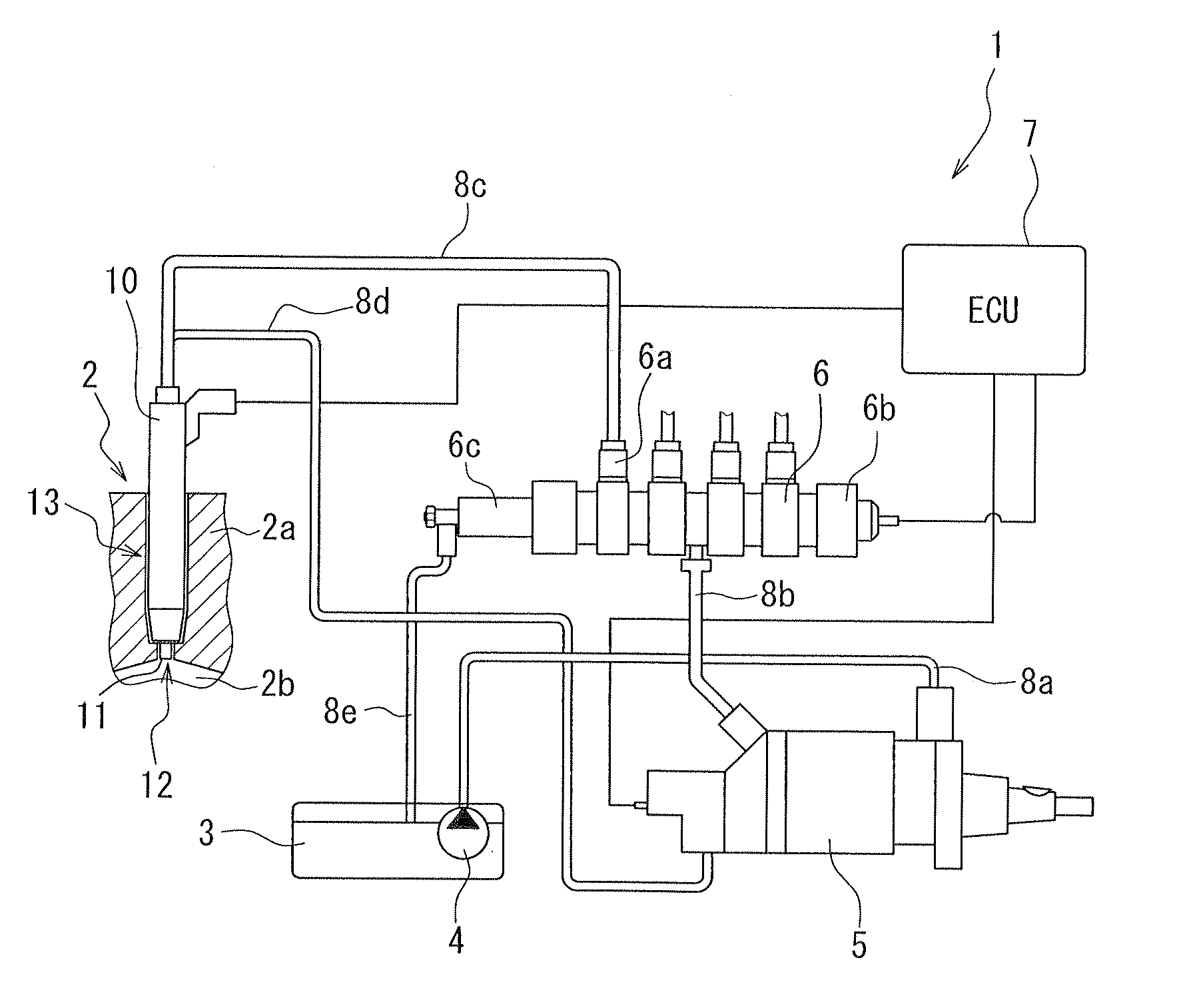
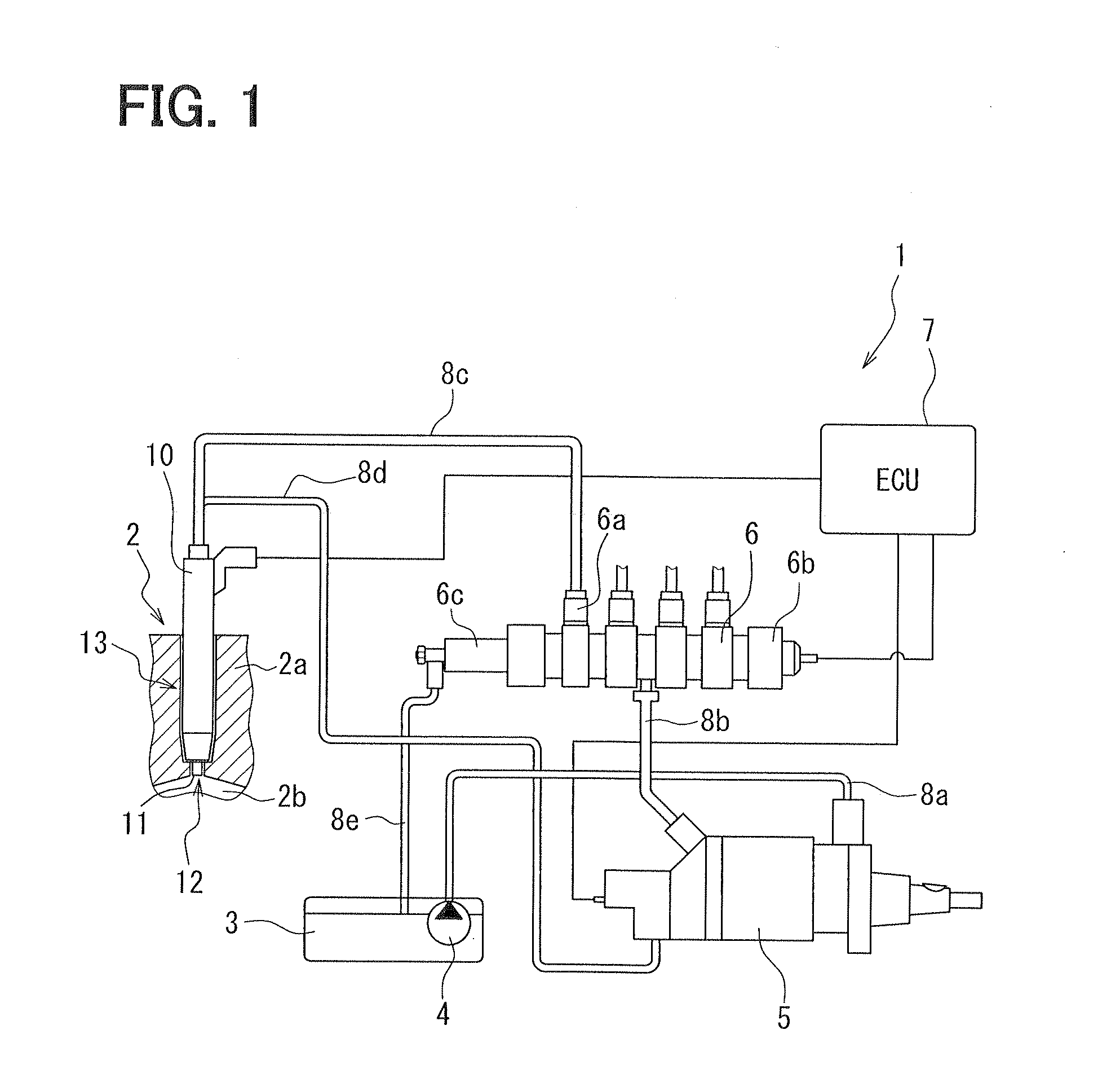
[0039]FIG. 1 is a block diagram of a fuel supply system 1 according to a first embodiment in the present invention. A fuel injection device 10 of the first embodiment is used in the fuel supply system 1. The fuel supply system 1 supplies fuel to an internal combustion engine 2. The combustion engine 2 is a multi-cylinder diesel engine. A head member 2a of the combustion engine 2 defines a combustion chamber 2b. The fuel supply system 1 is a direct injection fuel supply system. The fuel injection device 10 injects fuel directly to an inside of the combustion chamber 2b. The fuel supply system 1 includes a fuel tank 3, a feed pump 4, a high-pressure fuel pump 5, a common rail 6, an electric control unit (ECU) 7, and the fuel injection device 10.

[0040]The feed pump 4 is an electrically driven pump. The feed pump 4 is housed in the fuel tank 3. The feed pump 4 is connected to the high-pressure fuel pump 5 through a fuel pipe 8a. The feed pump 4 applies a predetermined feed pressure to t...

second embodiment

[0089]FIG. 10 is an enlarged cross-sectional view of a fuel injection device 210 of a second embodiment according to the present invention. In the following embodiments, similar components will be indicated by the same reference numerals and will not be described redundantly for the sake of simplicity. The details of the similar components are referred in the above described embodiment. The fuel injection device 210 can be applied to the fuel supply system 1 instead of the fuel injection device 10.

[0090]The fuel injection device 210 includes orifice members 250a, 250b, instead of the orifice member 50 of the first embodiment. The orifice members 250a, 250b are formed in a column shape or a circular disk shape to be stacked with each other in an axial direction. The orifice members 250a, 250b define a plurality of fuel passages. In the orifice members 250a, 250b, main supply passages 33a, 33b are defined to cause the longitudinal hole 61 to communicate with the nozzle needle housing ...


PUM


Abstract

A fuel injection device includes a cylinder defining a pressure chamber at an end portion of a nozzle needle. In the cylinder, a floating plate is provided as a controlling member of fuel pressure. An orifice member and a nozzle body are lined by an annular positioning member, using a circular peripheral surface of the orifice member and a circular peripheral surface of the nozzle body as a reference surface. Thereby, radial locations of the nozzle body and the orifice member are defined. Furthermore, a location of the floating plate is defined by the nozzle body with the nozzle needle. Therefore, the floating plate can be located to a proper location relative to the orifice member.

Description

CROSS REFERENCE TO RELATED APPLICATION[0001]This application is based on Japanese Patent Applications No. 2010-281996 filed on Dec. 17, 2010, and No. 2011-198460 filed on Sep. 12, 2011, the contents of which are incorporated herein by reference in its entirety.TECHNICAL FIELD[0002]The present invention relates to a fuel injection device, which controls fuel pressure applied to a valve member that allows or interrupts fuel injection from injection holes.BACKGROUND ART[0003]Patent documents 1 to 3 (EP 1656498B1, JP 06-108948A, JP 4054621B2 (corresponding to U.S. 2003 / 0052198A1)) describe regarding fuel injection devices that have a pressure chamber and a pressure control mechanism. The pressure chamber applies fuel pressure to a valve member that allows or interrupts fuel injection from injection holes. The pressure control mechanism controls the inside pressure of the pressure chamber to move the valve member. In the fuel injection devices, it is proposed to use a pressure-response t...

Claims


Application Information

Patent Timeline
IPC IPC(8): F02M69/04
CPCF02M47/027F02M61/168F02M2200/8061F02M2547/008F02M2200/8015F02M2547/001
Inventor ADACHI, NAOFUMIYAMASHITA, TSUKASA
Owner DENSO CORP
Why Eureka
Try Eureka