Electrically powered bolt setting device

Inactive Publication Date: 2012-06-21
HILTI AG
View PDF20 Cites 3 Cited by
  • Summary
  • Abstract
  • Description
  • Claims
  • Application Information

AI Technical Summary

Benefits of technology

[0023]Under certain circumstances, due to the present invention, a fully-automatic energy adjustment is possible. That is, a user of the invented bolt setting device need not decide what drive energy is selected for the next driving process. The device will make this decision for the user. Because the optimum driving energy is used for each fastening point, the fastening quality is improved. For example, the tendency to fracture masonry due to excessive driving energy can be reduced. Also, under certain circumstances, less excess energy has to be dissipated in the bolt setting devic

Problems solved by technology

These solutions cannot be readily transferred

Method used


Image

  • Electrically powered bolt setting device
  • Electrically powered bolt setting device
  • Electrically powered bolt setting device

Examples


Example

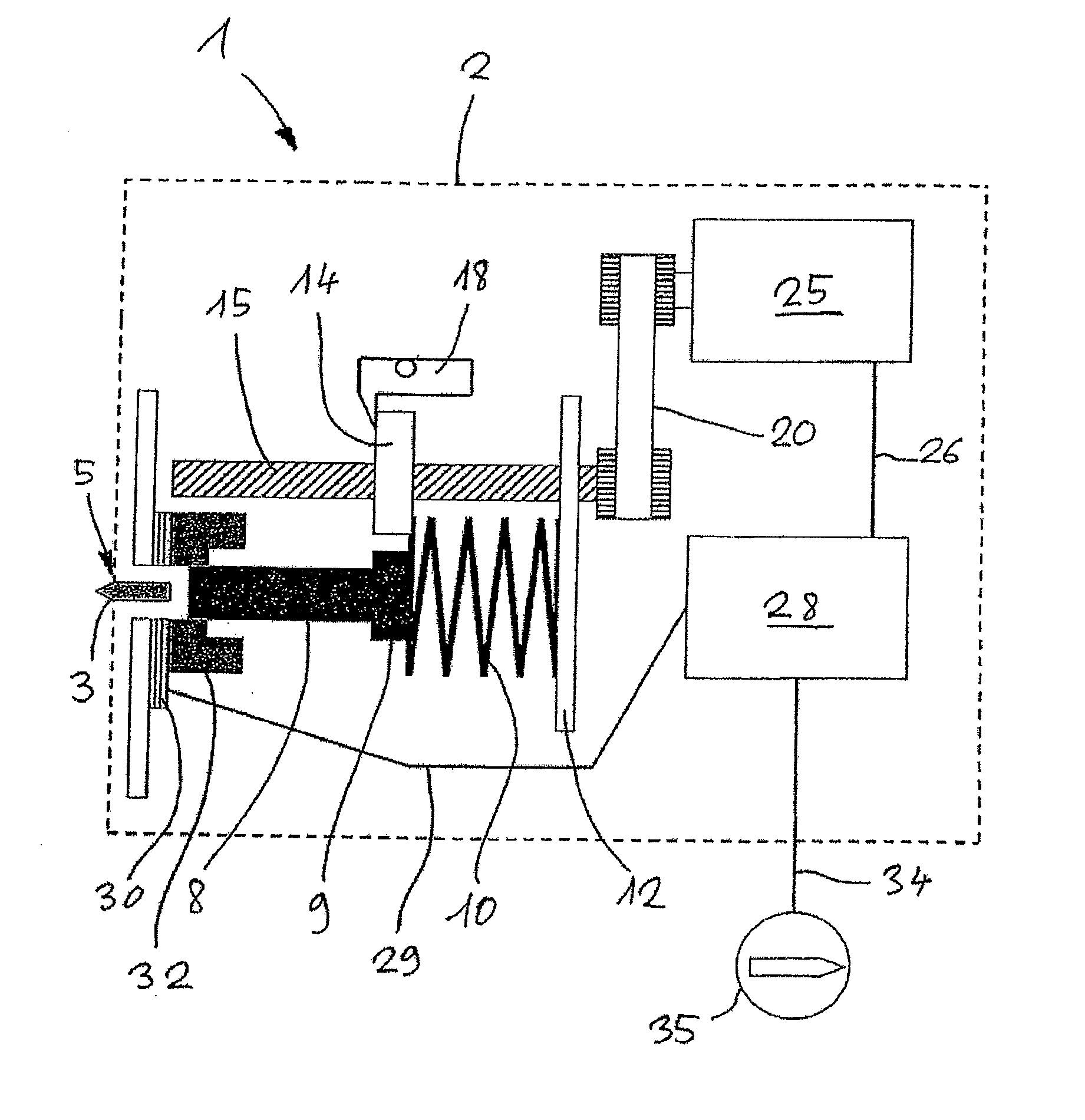
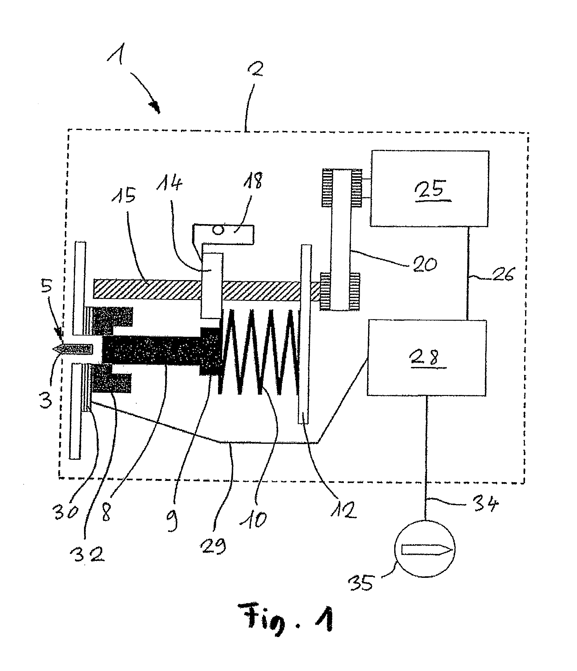
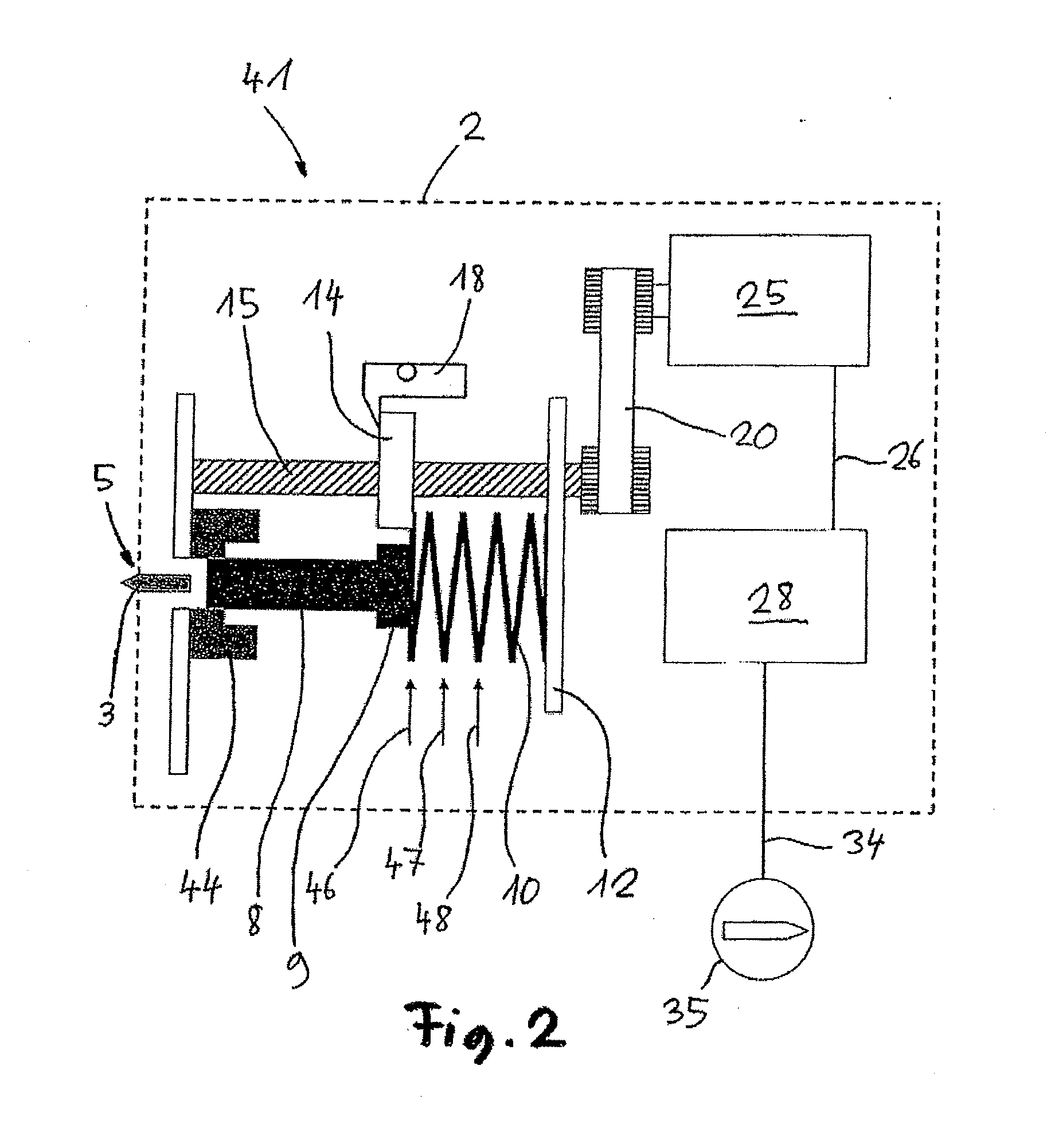
[0028]The bolt setting device according to this invention is a hand-held driving device, for instance, like that disclosed in FIGS. 1-4 of the associated description of German Patent Disclosure DE 10 2006 000 517 A1. The bolt setting device comprises a spring as a driving spring element and is thus also designated as spring nailer. The spring is tensioned by an electric motor which drives a recirculating ball screw via a toothed belt or a gear wheel- or friction-wheel transmission. A rotational movement of the threaded spindle is converted into a linear movement of the spindle nut via a spindle nut mounted in a rotationally secured manner to the threaded spindle.

[0029]FIGS. 1-3 present a bolt setting device 1; 41; 51 with a housing 2 shown in a simplified cross section. The bolt setting device 1; 41; 51 comprises a magazine for fastening elements 3, in particular bolts—a supply is held in the magazine. The bolt setting device 1; 41; 51 further comprises a handle which can be grasped...


PUM

PropertyMeasurementUnit
Pressureaaaaaaaaaa
Energyaaaaaaaaaa
Chemical energyaaaaaaaaaa

Abstract

The invention relates to an electrically powered bolt setting device (1) for setting of fastening elements (3) with a spring unit (10) which acts as an intermediate energy store in order to store energy, originating from an electric drive (25), in the bolt setting device (1), and said energy can be released suddenly during a bolt setting process.
In order to create an electrically powered bolt setting device which has a simple design and can be produced at low cost and/or is low in cost to operate, the spring unit (10) cooperates with a unit to adjust the interim-stored energy.

Description

TECHNICAL FIELD[0001]The invention relates to an electrically powered bolt setting device for setting of fastening elements with a spring unit which acts as an intermediate energy store in order to store energy, originating from an electric drive, in the bolt setting device, said energy can be released suddenly during a bolt setting process, characterized in that the spring unit cooperates with a unit to adjust the interim-stored energy.PRIOR ART[0002]Now the electrically powered bolt setting device relates preferably to a hand-operated driving device for fastening elements, such as that disclosed in German Patent Disclosure DE 10 2006 000 517 A1, for example. A similar driving device with a control unit comprising at least one timer is known from the international publication WO 2007 / 142997 A2. The timer monitors the time needed for a partial or complete recoil stroke, for example. A bolt setting device that is powered by liquid fuel and comprises an automatic control unit for adju...

Claims


Application Information

Patent Timeline
IPC IPC(8): B25C1/00B25C1/06B25C1/08B25C1/04
CPCB25C1/06
Inventor BERTSCH, KLAUSFIELITZ, HARALDFRANZ, KARLBLESSING, MATTHIASSCHIESTL, ULRICH
Owner HILTI AG
Why Eureka
Try Eureka