Method of controlling and regulating the deflection angle of a tailplane in a hybrid helicopter

a tailplane and hybrid technology, applied in the direction of rotors, propellers, position/direction control, etc., can solve the problems of reducing the amount of power dedicated to providing traction, affecting the flight speed of the helicopter, so as to improve the range, optimize the power consumption of the aircraft, and increase the range of the aircraft.

Active Publication Date: 2012-06-21
EUROCOPTER
View PDF22 Cites 34 Cited by
  • Summary
  • Abstract
  • Description
  • Claims
  • Application Information

AI Technical Summary

Benefits of technology

[0069]The control and regulation method in accordance with the invention presents the advantage of optimizing the power consumed by the aircraft for given speed of advance and attitude.
[0070]The control and regulation method in accordance with the invention also presents the advantage of increasing the range the aircraft can travel. Thus, in order to optimize the range, it suffices to set a level attitude setpoint, to set an indicated air speed (IAS) equal to the most economic cruising speed, and to implement the relationship for managing the angular position of the tailplane in accordance with the invention. In the same manner, e.g. when climbing with a shallow slope, it suffices to have an attitude setpoint equal to the slope of the climbing flight path and to have a climb rate that is a function of said slope and said setpoint IAS, and then to implement the relationship for managing the angular po

Problems solved by technology

Those two types of regulation cannot be juxtaposed in order to regulate the power of a rotorcraft fitted with propeller thruster(s), since the regulation techniques are in opposition.
Furthermore, for a rotorcraft fitted with propeller thruster(s), regulation of said propeller thruster(s) whereby the pilot varies propulsion propeller pitch directly might give rise to propeller damage as a result of sudden variations in the driving torque delivered thereto.
These operating conditions thus lead to a reduced amount of power dedicated to providing traction being delivered to the rotor(s).
Nevertheless, as from a certain speed of advance, a conventional helicopter can

Method used


Image

  • Method of controlling and regulating the deflection angle of a tailplane in a hybrid helicopter
  • Method of controlling and regulating the deflection angle of a tailplane in a hybrid helicopter
  • Method of controlling and regulating the deflection angle of a tailplane in a hybrid helicopter

Examples


Embodiment Construction

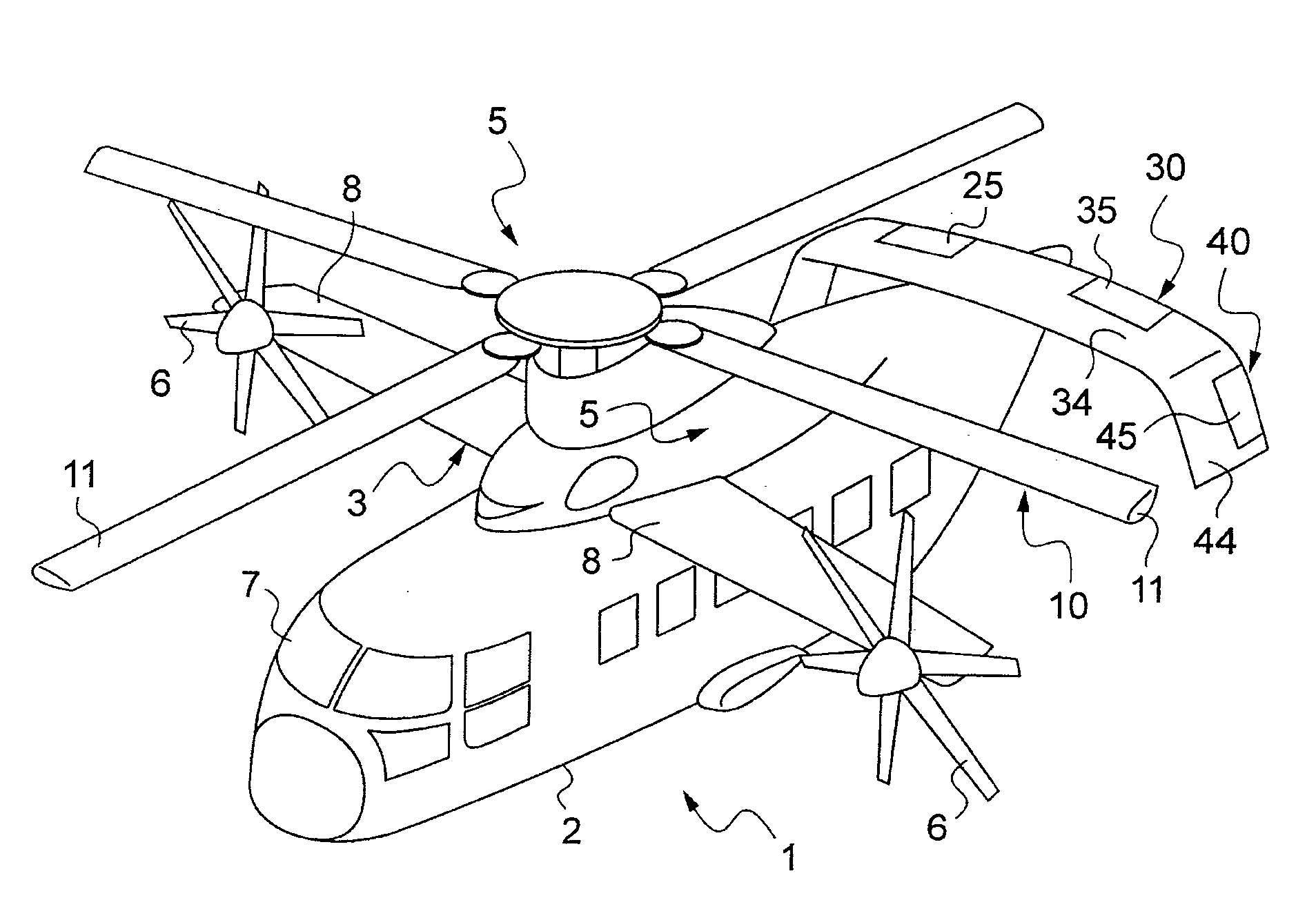
[0079]In the meaning of the present application, the term “hybrid helicopter” designates a rotorcraft fitted with at least one propeller type thruster, with regulation adapted both to the operation of the lift and possibility also propulsion rotor(s) and also to the operation of the propeller(s).

[0080]Unless indicated explicitly or implicitly to the contrary, the terms “rotor” or “main rotor” designate a rotary wing of the rotorcraft.

[0081]Unless indicated explicitly or implicitly to the contrary, elements that are structurally and functionally identical and present in more than one of the figures are given the same numerical or alphanumerical references in each of them.

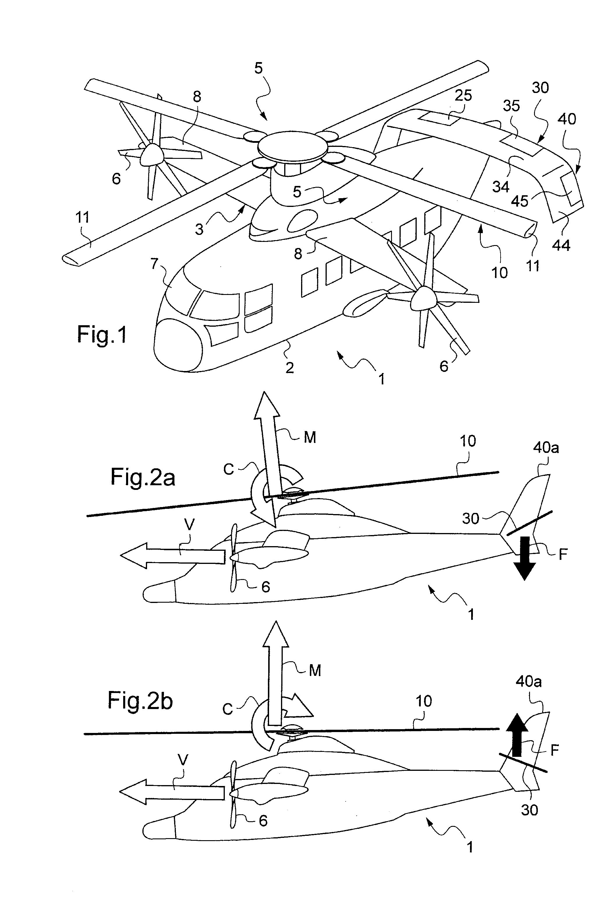
[0082]With reference to FIG. 1, in particular, the hybrid helicopter 1 comprises a fuselage 2 with a cockpit 7 provided at the front thereof, a main rotor 10 for driving blades 11 in rotation under drive from two turbine engines 5 located on top of the fuselage 2 (not shown in FIG. 1 because of the presence of fairin...


PUM


Abstract

A method of controlling and regulating a rotorcraft presenting a speed of advance that is high and stabilized, the rotorcraft including at least a main lift rotor (10), at least one variable pitch propulsion propeller (6), and at least one power plant for driving the main rotor(s) (10) and at least one propeller (6), said method consisting in using a first loop for regulating pitch or attitude, and a second loop for regulating speed by means of a control over the mean pitch of the propulsion propeller(s) (6), wherein the method further consists in controlling the deflection angle of a horizontal tailplane (30, 25, 35) by using a third loop for controlling and regulating said deflection angle of the horizontal tailplane (30, 25, 35) in order to minimize the total power consumed by the main rotor (10) and the propulsive propeller(s) (6), for a given speed and attitude.

Description

CROSS REFERENCE TO RELATED APPLICATIONS[0001]This application claims the benefit of FR 10 01789 filed on Apr. 27, 2010, the disclosure of which is incorporated in its entirety by reference herein.BACKGROUND OF THE INVENTION[0002](1) Field of the Invention[0003]The present invention relates to the general technical field of automatic or semi-automatic flight control systems, and more particularly to a method of controlling and regulating the deflection angle of a moving tailplane of a particular type of rotorcraft, specifically a hybrid helicopter.[0004]More particularly, the present invention relates to a rotorcraft and to its system for controlling a movable tailplane, with the deflection angle of the tailplane being determined as a function of specific parameters in stabilized flight at a high cruising speed.[0005](2) Description of Related Art[0006]The term “rotorcraft” is used to designate an aircraft in which lift is provided in full or in part by one (or more) large-diameter p...

Claims


Application Information

Patent Timeline
IPC IPC(8): B64C27/54
CPCB64C2027/8281B64C27/26
Inventor EGLIN, PAULQUEIRAS, NICOLASBARRACO, ANDREMALBURET, FRANCOIS
Owner EUROCOPTER
Why Eureka
Try Eureka