Side Skirt for a Pulled Vehicle

a side skirt and pull-up technology, applied in the direction of roofs, transportation and packaging, vehicle arrangements, etc., can solve the problems of large amount of engine power required to overcome the aerodynamic, the aerodynamic drag of the bluff shape is mainly, and the fuel cost of heavy transport vehicles, so as to reduce the aerodynamic drag behind the vehicle, reduce the turbulence zone along the whole length of the vehicle, and reduce the pressure drop

Active Publication Date: 2012-06-21
WABCO EURO BVBA SPRL
View PDF2 Cites 16 Cited by
  • Summary
  • Abstract
  • Description
  • Claims
  • Application Information

AI Technical Summary

Benefits of technology

[0030]In an embodiment according to the invention, the flow conductor extends over the whole length of the vehicle to guide an air stream from the front of the vehicle along the underside of the body portion to the back of the vehicle. Advantageously, turbulent zones along the whole length of the vehicle are reduced. Components, like pillars and storage containers which could cause disturbances of the airflow are arranged behind the flow conductor and no longer adversely affect the guided airflow.
[0031]It is advantageous to sustain the flow path to the back of the body portion. Herewith also the aerodynamic drag behind the vehicle is reduced. The guidance of air to the back of the vehicle reduces the pressure drop behind the vehicle, which positively affect the aerodynamic performance of the total vehicle combination.
[0032]A further embodiment of the present invention comprises a longitudinal flow conduct...

Problems solved by technology

The aerodynamic drag of a bluff shape is mainly due to the pressure difference of the front and rear faces of the body, with respect to the environment pressure, with only a secondary contribution due to skin friction.
Fuel economy and the associated fuel cost of heavy transport vehicles are very important issues within the operational cost of national and international transport companies.
A large amount of engine power is required to overcome the aerodynamic forces that are acting on a road vehicle, due to the passage of the vehicle through air.
Besides reducing the aerodynamic drag with special designed devices or aerodynamically well streamlined bodies, also other measures may positively effect the fuel consumption of vehicles.
Due to the aerodynamic instabilities in the f...

Method used


Image

  • Side Skirt for a Pulled Vehicle
  • Side Skirt for a Pulled Vehicle
  • Side Skirt for a Pulled Vehicle

Examples


Embodiment Construction

[0057]In the end of this detailed description a legend is presented indicating the names of components with corresponding reference numbers.

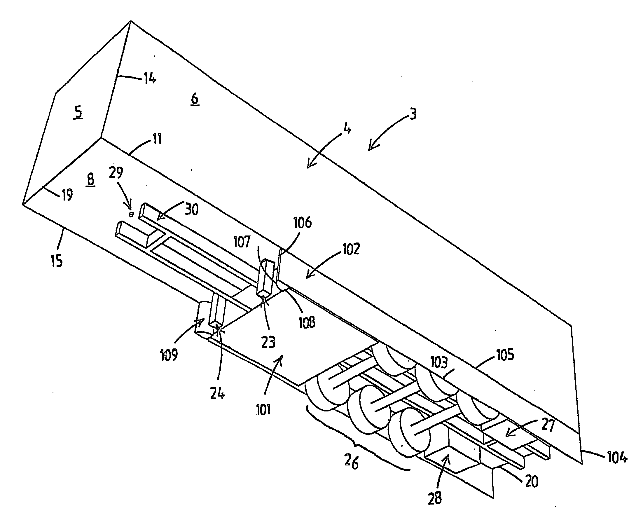
[0058]The present invention is an aerodynamic drag reduction device to be used with wheeled vehicles of a type generally having a vehicle body portion supported by one or more wheel assemblies located below the body volume where it is exposed to an airflow that contributes to the total drag of the vehicle. The proposed aerodynamic device, which will be named as longitudinal flow conductor, can be applied on different transportation vehicles including automobiles, trains, aircraft or any other vehicle having one or more wheel assemblies located or extending below a body portion of the vehicle which is exposed to an airflow resulting in aerodynamic drag.

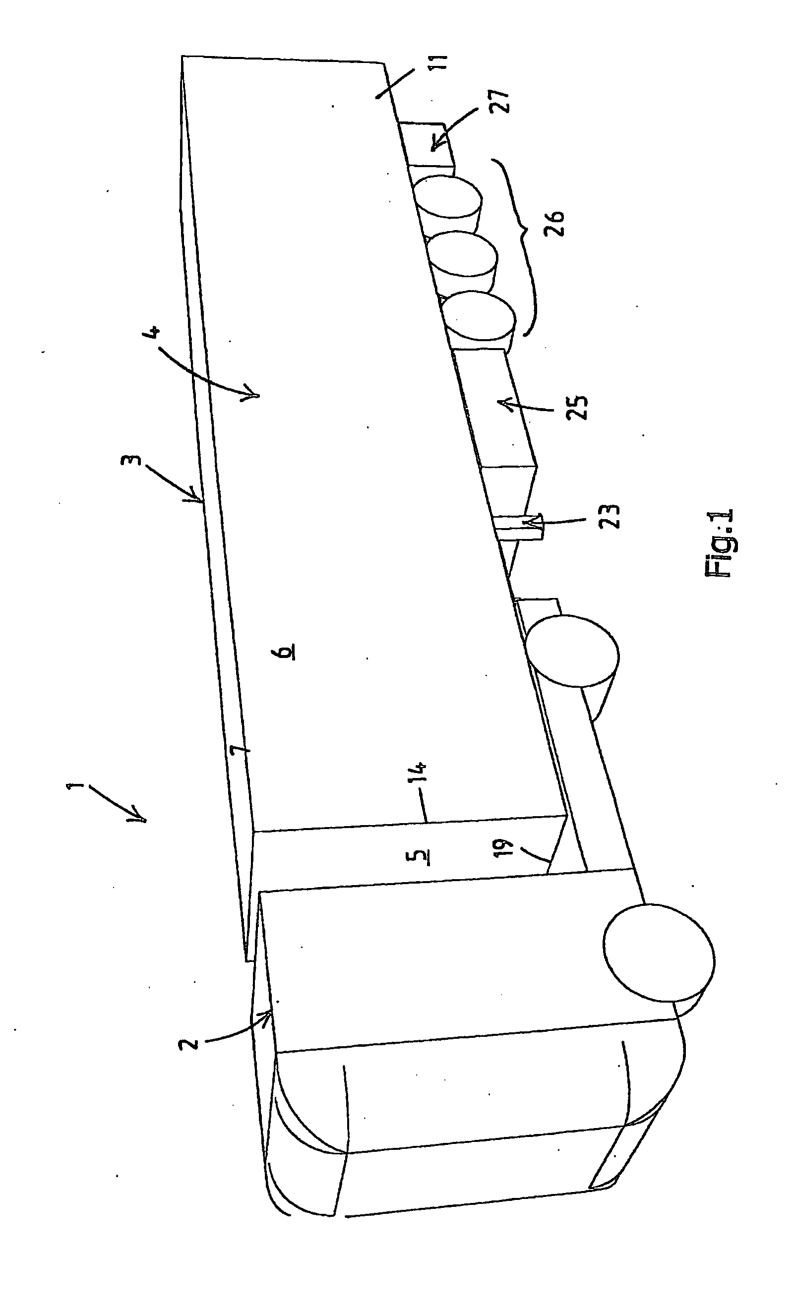
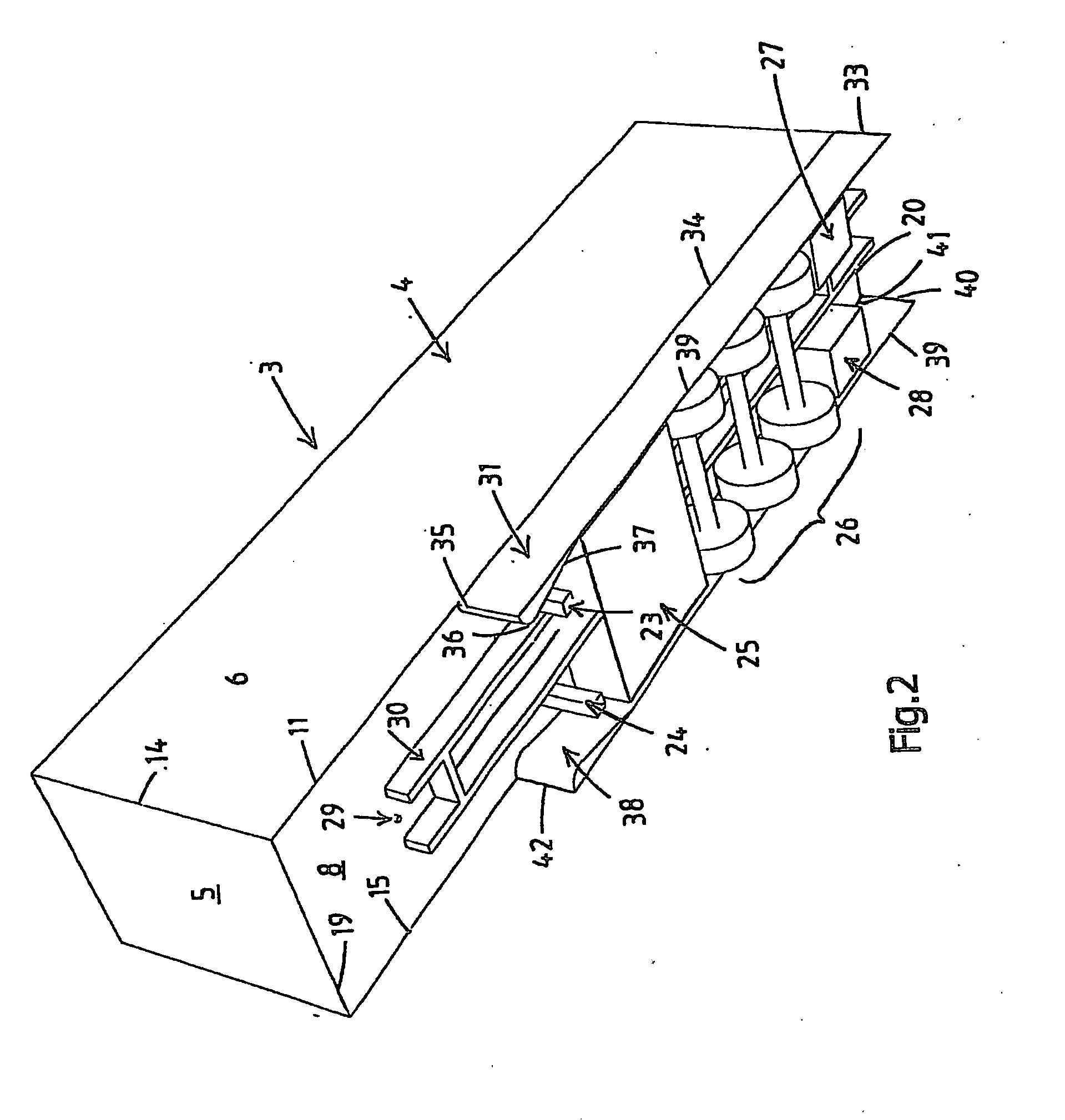
[0059]In FIGS. 1-18 of the drawings and in the following discussion, a conventional trailer of a tractor-trailer combination and a rigid truck with a drawbar and a lorry have been selected as repre...


PUM


Abstract

The present invention relates to a device for minimizing the aerodynamic drag that results when tractors, trailers, rigid trucks, lorries, and other vehicles are moving through air. In particular the invention relates to a plate-shaped flow conductor having a front edge, a lower edge, a rear edge and an upper edge. The flow conductor is mountable along the upper edge in a substantially vertical position to a body portion of a pulled vehicle of a vehicle combination of at least two pivotally connected vehicles. When mounted the flow conductor extends at least partially under the body portion in a longitudinal direction of the pulled vehicle. Characteristic for the flow conductor according to the invention is that the flow conductor comprises locally in conjunction with the front edge a thickened portion, which has a streamlined outer contour in a cross section transversally to the front edge.

Description

CROSS-REFERENCE TO RELATED APPLICATION[0001]This application is the National Phase of International Application no. PCT / NL2008 / 000187, filed 4 Aug. 2008, which claims priority to and the benefit of U.S. provisional patent application No. 60 / 955,524, filed 13 Aug. 2007, and NL patent application no. 1034363, filed 11 Sep. 2007, the contents of which are incorporated by reference as if fully set forth herein.FIELD OF THE INVENTION[0002]The present invention relates to a flow conductor for minimizing the aerodynamic drag that results when tractors, trailers, rigid trucks, lorries, and other vehicles are moving through air. In particular the invention relates to a plate-shaped flow conductor for use as a side skirt having a front edge, a lower edge, a rear edge and an upper edge. The flow conductor is mountable along the upper edge in a substantially vertical position to an outer lower edge of a body portion of a pulled vehicle of a vehicle combination of at least two pivotally connecte...

Claims


Application Information

Patent Timeline
IPC IPC(8): B62D35/00
CPCB62D35/008B62D35/001B62D35/02B62D37/02
Inventor VAN RAEMDONCK, GANDERT MARCEL RITA
Owner WABCO EURO BVBA SPRL
Why Eureka
Try Eureka