Piezoelectric micro energy harvester and manufacturing method thereof

a technology of micro-energy harvester and manufacturing method, which is applied in the direction of piezoelectric/electrostrictive transducer, generator/motor, transducer type, etc., can solve the problems of energy harvester life, energy harvester influence, environmental pollution, etc., and achieves simple structure, easy to form, and small size

Inactive Publication Date: 2012-06-21
ELECTRONICS & TELECOMM RES INST
View PDF4 Cites 13 Cited by
  • Summary
  • Abstract
  • Description
  • Claims
  • Application Information

AI Technical Summary

Benefits of technology

[0019]Further, the present invention provides a piezoelectric micro energy harvester capable of easily using various kinds of materials as a piezoelectric film serving as an energy conversion functional film, and a method for manufacturing the piezoelectric micro energy harvester.
[0020]Further, the present invention provides a piezoelectric micro energy harvester which can be easily mass-manufactured with the low manufacturing costs, and a method for manufacturing the piezoelectric micro energy harvester.
[0023]Accordingly, the piezoelectric micro energy harvester of the present invention has a small size and a simple structure, can be formed in a microstructure having any shape, and easily form and uses various kinds of materials as the piezoelectric film serving as the energy conversion functional film.
[0024]Further, the present invention is advantageous in that it is possible to implement the piezoelectric micro energy harvester responding to bands over the broadband frequency, convert the mechanical energy generated in a surrounding environment to the electrical energy, and generate power by itself.

Problems solved by technology

In a general sensor, it is necessary to periodically change a battery in order for the sensor to receive power from a battery mounted inside the sensor, and at this time the entire sensor itself should be detached and attached, so that there occurs a problem in maintenance costs, life of a battery, influence by a high temperature, environment pollution, etc.
However, the development of an energy harvester, which is a fundamental solution for operating a sensor module without power in various environments of various places, has been unfinished, and international advanced research groups are conducting research on the application of vibration, sun, wind, heat, etc. as power resources.
However, according to these methods, the structures in various forms are mechanically processed, arranged, and assembled, so that there is a problem of the increase of the manufacturing costs.
Therefore, in the event of manufacturing the piezoelectric micro energy harvester by using the conventional semiconductor manufacturing process, there is a problem of the large manufacturing costs, long manufacturing time, and the decrease of a manufacturing yield.
Such a method is a process of processing front and back surfaces of a substrate, so that the process requires a large cost and is generally implemented by a wet etching using a crystalline orientation of the silicon substrate itself, so that it is impossible to optionally control a geometric form, such as a depth and a shape of a microstructure of the piezoelectric micro energy harvester, thereby resulting in the limitation of the miniaturization of the piezoelectric micro energy harvester.
Further, in implementing the structure of the piezoelectric micro energy harvester by using a high-priced substrate, such as the SOI (Silicon-On-Insulator) structure, the manufacturing costs of the piezoelectric micro energy harvester further increases.
For these methods, it is necessary to develop a unique forming process and bonding method according to each of the piezoelectric film materials to be used and the alignment equipment is required, so that the manufacturing costs is disadvantageously high.
In the meantime, mechanical vibration frequency spectrums of various bands exist in nature and it is extremely difficult to individually control the spectrums, so that the mechanical energy has to be converted to the electrical energy even in the various external mechanical frequencies in order to actually implement the piezoelectric micro energy harvester.

Method used


Image

  • Piezoelectric micro energy harvester and manufacturing method thereof
  • Piezoelectric micro energy harvester and manufacturing method thereof
  • Piezoelectric micro energy harvester and manufacturing method thereof

Examples


Embodiment Construction

[0030]Hereinafter, an exemplary embodiment of the present invention will be described with reference to the accompanying drawings. The construction and the operation effects of the present invention will be clearly appreciated through the detailed descriptions below.

[0031]In describing a piezoelectric micro energy harvester according to an embodiment of the present invention, a cantilever-shaped suspended microstructure responding to a frequency of a surrounding environment is exemplified, but a basic structure of the piezoelectric micro energy harvester of the present invention is not limited to a specific form.

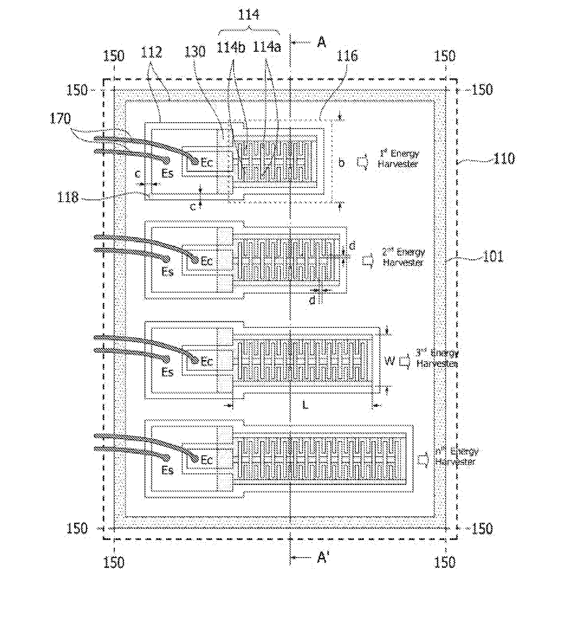
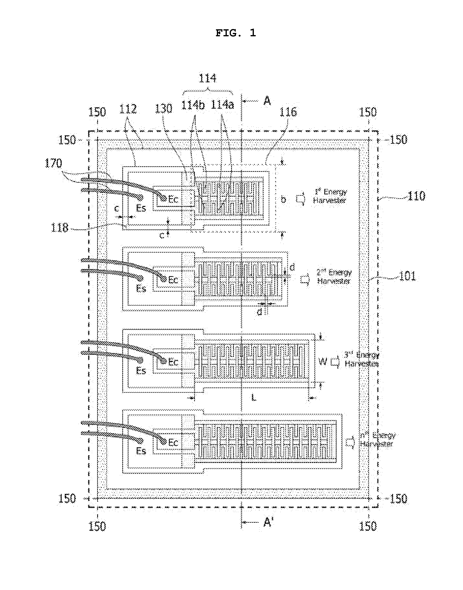
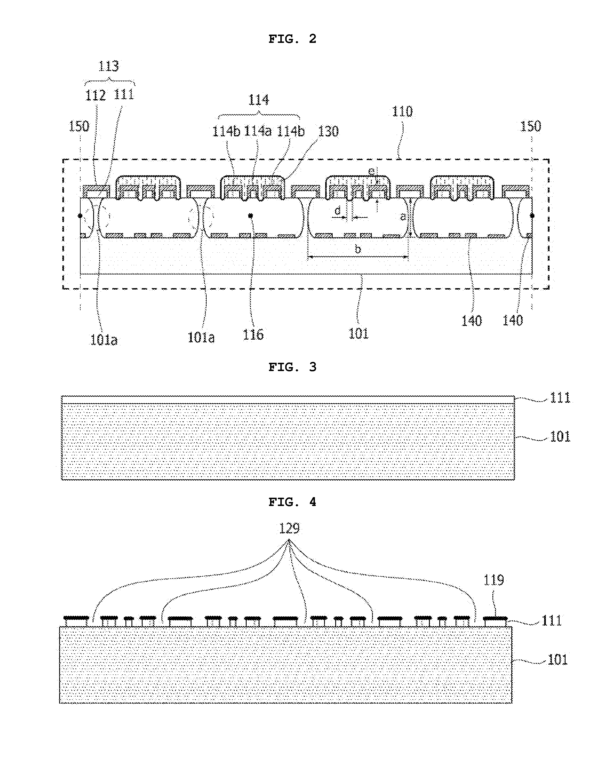
[0032]FIG. 1 is a plane view illustrating the piezoelectric micro energy harvester according to an embodiment of the present invention, and FIG. 2 is a sectional view illustrating the piezoelectric micro energy harvester of FIG. 1 taken along AA′ line.

[0033]Referring to FIGS. 1 and 2, the piezoelectric micro energy harvester 110 according to the present invention generates e...


PUM

PropertyMeasurementUnit
widthaaaaaaaaaa
widthaaaaaaaaaa
thicknessaaaaaaaaaa

Abstract

Disclosed is a piezoelectric micro energy harvester and manufacturing method thereof, the method including: forming an insulation film on a substrate; patterning the insulation film and forming an electrode pad pattern, a center electrode pattern, and a side electrode pattern; forming an open cavity at an inside of the substrate for suspension of the center electrode pattern and the side electrode pattern; disposing a conductive film on the electrode pad pattern, the center electrode pattern, and the side electrode pattern and forming electrode pads, a center electrode, and a side electrode; and forming a piezoelectric film so as to cover a space between the center electrode and the side electrode and upper surfaces of the center electrode and the side electrode.

Description

CROSS-REFERENCE TO RELATED APPLICATIONS[0001]This application is based on and claims priority from Korean Patent Application No. 10-2010-0131434, filed on Dec. 21, 2010, with the Korean Intellectual Property Office, the disclosure of which is incorporated herein in its entirety by reference.BACKGROUND OF THE INVENTION[0002]1. Field of the invention[0003]The present invention relates to a piezoelectric micro energy harvester which converts mechanical energy generated in a surrounding environment to electrical energy and generates power by itself, and a method of manufacturing the piezoelectric micro energy harvester. More particularly, the present invention relates to a piezoelectric micro energy harvester, which has a small-sized simple structure and uses various kinds of materials as a piezoelectric film serving as a functional film for energy conversion, and a method of manufacturing the piezoelectric micro energy harvester.[0004]2. Description of the Prior Art[0005]In a general s...

Claims


Application Information

Patent Timeline
Patent Type & Authority Applications(United States)
IPC IPC(8): H02N2/18H01L41/22
CPCH02N2/188Y10T29/42H01L41/316H01L41/29H01L41/318H01L41/317H01L41/31H01L41/1136H10N30/306H10N30/06H10N30/078H02N2/00H02N2/18H10N30/80H10N30/07H10N30/076H10N30/077
Inventor JUN, CHI HOONKO, SANG CHOONMOON, JONG TAE
Owner ELECTRONICS & TELECOMM RES INST
Why Eureka
Try Eureka