Image sensor unit and image reader

a technology of image sensor and image reader, which is applied in the direction of instruments, electrical appliances, optics, etc., can solve the problems of inability to illuminate light in the infrared region, affect authenticity determination, etc., and achieve the effect of stable image data

Inactive Publication Date: 2012-06-21
CANON COMPONENTS INC
View PDF9 Cites 28 Cited by
  • Summary
  • Abstract
  • Description
  • Claims
  • Application Information

AI Technical Summary

Benefits of technology

[0013]The present invention is made in view of these situations. It is an object of the present invention to provide an image sensor unit and an image reader that are capable of acquiring stable image data even if variation in ambient temperature causes a temperature shift in light emission wavelength and in turn causes variation in luminance.

Problems solved by technology

Thus, there is a possibility that, in a certain ambient temperature, a region with large variation in absorptivity of light of emission wavelengths in the infrared region owing to plastic matches with a region of temperature shift of the light emission wavelength owing to temperature variation, thereby causing instability in illuminance of light of the emission wavelengths in the infrared region.
This in turn causes instability in an amount of light reflected from a reading surface of a paper sheet during reading, which affects determination of authenticity.

Method used


Image

  • Image sensor unit and image reader
  • Image sensor unit and image reader
  • Image sensor unit and image reader

Examples


embodiment 1

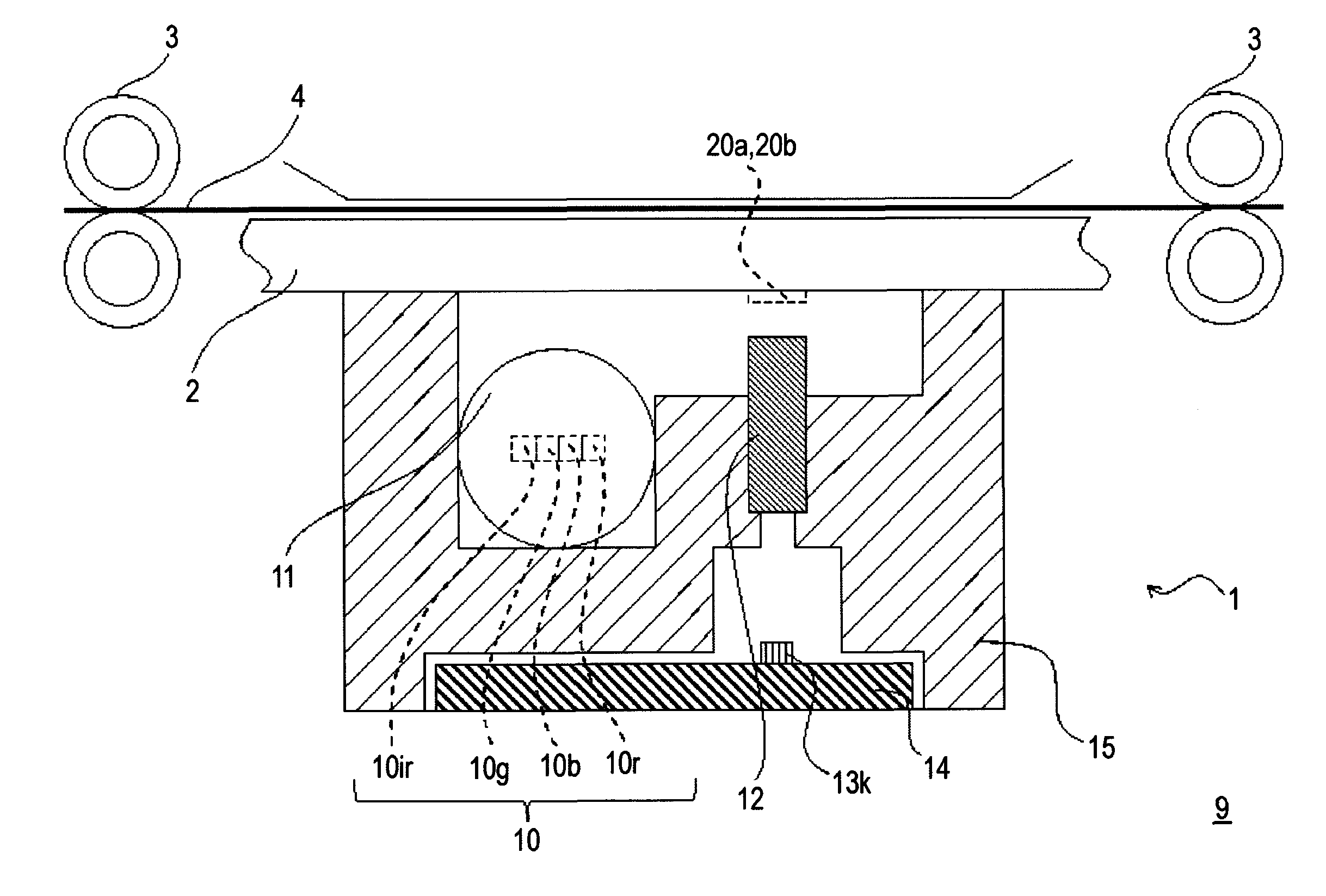
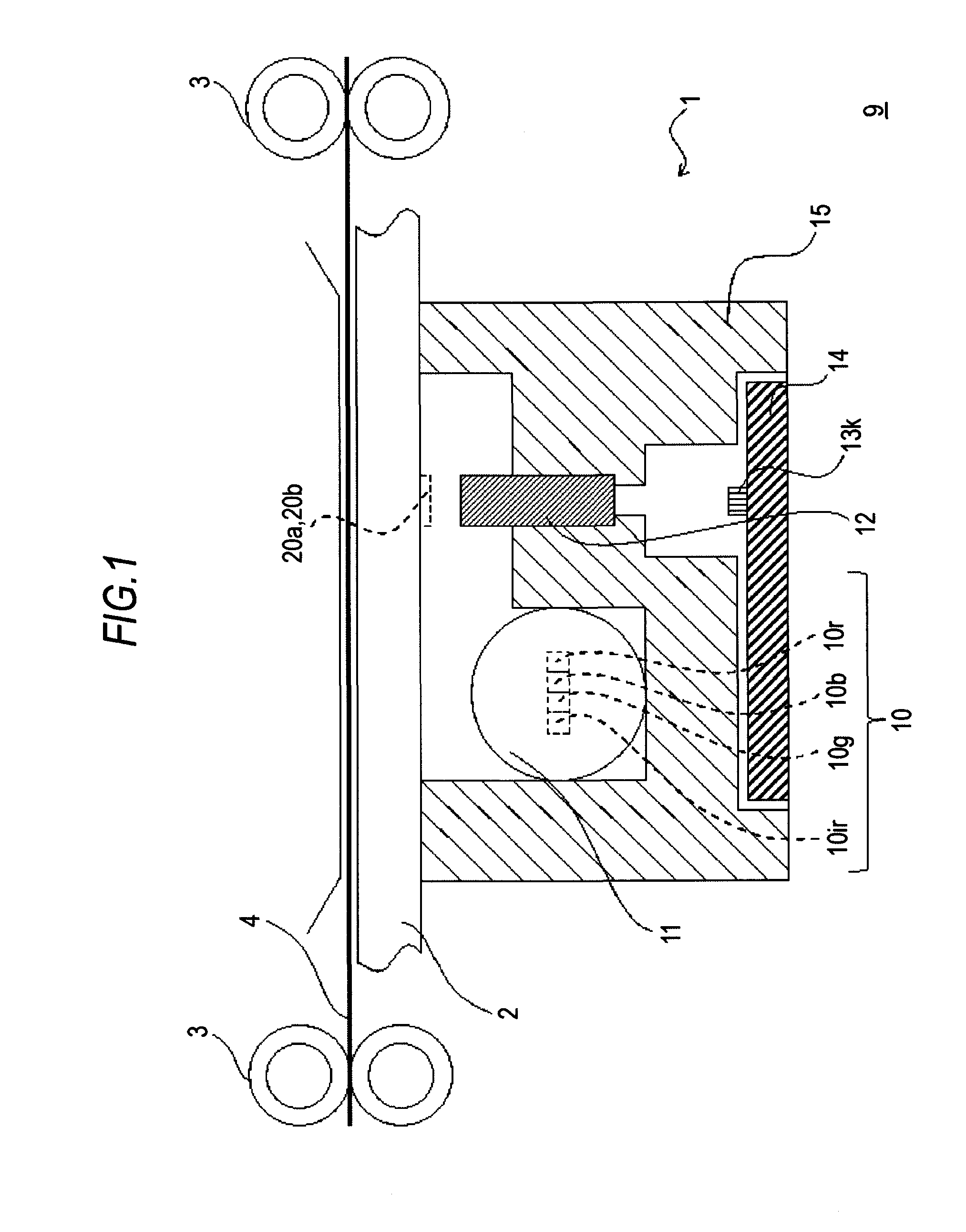
[0078]FIG. 5A is an elevational view showing a structure of an image sensor unit 1 to which the present invention is applicable. FIG. 5B is a plan view showing the structure of the image sensor unit 1 to which the present invention is applicable.

[0079]FIG. 6 is a block diagram showing a configuration of the signal processor 17. As shown in FIG. 6, the signal processor 17 is electrically connected to the image sensor unit 1.

[0080]Reference numerals 20a and 20b denote white reference plates as white reference means that are provided on the back of the cover glass 2 in the image sensor unit 1 and have a color of white. The white reference plates 20a and 20b are provided as a first white reference plate 20a arranged at the opposite side end away from the light source 10 and a second white reference plate 20b arranged at the side end with the light source 10, at positions that are on the opposite ends in the longitudinal direction of the rod lens array 12 and cover areas external to an i...

embodiment 2

[0105]FIG. 5A is the elevational view showing the structure of the image sensor unit 1 to which the present invention is applicable. FIG. 5B is the plan view showing the structure of the image sensor unit 1 to which the present invention is applicable.

[0106]FIG. 9 is a block diagram showing another configuration of the signal processor 17. As shown in FIG. 9, the signal processor 17 is electrically connected to the image sensor unit 1.

[0107]Reference numerals 20a and 20b denote white reference plates as white reference means that are provided on the back of the cover glass 2 in the image sensor unit 1 and have a color of white. The white reference plates 20a and 20b are provided as a first white reference plate 20a arranged at the opposite side end away from the light source 10 and a second white reference plate 20b arranged at the side end with the light source 10 at positions that are on the opposite ends in the longitudinal direction of the rod lens array 12 and cover respective ...

embodiment 3

[0132]FIG. 11A is an elevational view showing another structure of an image sensor unit 1 to which the present invention is applicable. FIG. 11B is a plan view showing another structure of the image sensor unit 1 to which the present invention is applicable.

[0133]FIG. 12 is a block diagram showing another configuration of the signal processor 17. As shown in FIG. 12, the signal processor 17 is electrically connected to the image sensor unit 1.

[0134]Reference numeral 20 denotes a white reference plate as white reference means that is provided on the back of the cover glass 2 in the image sensor unit 1 and has a color of white. The white reference plate 20 is provided at a position that is the opposite side end away from the light source 10 in the longitudinal direction of the rod lens array 12 and covers an area external to an image region across the banknote 4.

[0135]Here, the white reference plate 20 may be a plate-shaped component, or what is made by printing.

[0136]In this embodime...


PUM


Abstract

An illumination device includes a light guide made of plastic, and a light source including a light emitting element whose dominant wavelength is a light emission wavelength in an infrared region, and identifies a banknote. White reference plates are provided at positions that are at opposite ends of a rod lens array and cover respective areas external to an image region across the banknote. A correction coefficient is acquired by calculation. The calculation is made by correcting an illuminance such that IR correction data is substantially identical to IR reference data preliminarily stored in a memory circuit in a signal processor on the basis of IR white reference data representing a white reference illuminance generated from light reflected from the white reference plates. The correction coefficient is used for correcting IR image data when the banknote is read.

Description

CROSS-REFERENCE TO RELATED APPLICATIONS[0001]This application is based upon and claims the benefit of priority of the prior Japanese Patent Application No. 2010-284035, filed on Dec. 21, 2010 and the Japanese Patent Application No. 2011-236415, filed on Oct. 27, 2011, the entire contents of which are incorporated herein by reference.BACKGROUND OF THE INVENTION[0002]1. Field of the Invention[0003]The present invention relates to an image sensor unit and an image reader using the image sensor unit.[0004]2. Description of the Related Art[0005]As an image reader, an apparatus for reading a print pattern of a paper sheet has been proposed.[0006]Patent Document 1: Japanese Laid-open Patent Publication No. 2003-46726[0007]As described in Patent Document 1, the image sensor unit in the image reader (apparatus for reading a print pattern of a paper sheet) has a configuration that emits light having a light emission wavelength in an infrared region in order to identify authenticity of a bankn...

Claims


Application Information

Patent Timeline
Patent Type & Authority Applications(United States)
IPC IPC(8): H04N1/387
CPCH04N1/00013H04N2201/03183H04N1/00045H04N1/0005H04N1/00063H04N1/00087H04N1/0009H04N1/02835H04N1/0318H04N1/12H04N1/193H04N2201/03112H04N2201/03125H04N2201/03129H04N2201/03141H04N2201/03145H04N2201/0315H04N1/00031G07D7/121G07D7/205G07D7/1205G02B6/00H04N1/028H04N1/04H04N1/60
Inventor SHIMODA, SHUUICHI
Owner CANON COMPONENTS INC
Why Eureka
Try Eureka