
Electrical Energy Conversion Circuit Device

a circuit device and energy conversion technology, applied in the direction of power conversion systems, dc-dc conversion, instruments, etc., can solve the problems of mechanical stress, energy loss, and reduce the lifetime of the circuit device, and achieve the effect of low switching loss

Inactive Publication Date: 2012-06-21
KONINKLIJKE PHILIPS ELECTRONICS NV
View PDF6 Cites 29 Cited by
  • Summary
  • Abstract
  • Description
  • Claims
  • Application Information

AI Technical Summary

Benefits of technology

[0013]Since the controller is adapted to control the first and the second buck-boost converter such that the first and the second intermediate current are phase-shifted to each other, a current ripple of the sum of the first and the second intermediate current is reduced. It shall be understood that the circuit device of the present invention is set up such that the output capacitor receives that sum of the first and the second intermediate current. Due to the phase-shift, during one time period of a switching period, the first intermediate current is rising and the second intermediate current is falling. This operation mode, which is also referred to as interleaved operation of the first and the second buck-boost converter, has the advantage that a current stress effective at the output capacitor and an input capacitor providing the direct input voltage can be reduced by 60% compared to a single buck-boost converter converting the same amount of power.
[0086]In another preferred embodiment of the electrical energy conversion circuit device, the first and the second buck-boost converter each comprise a silicon-carbide- (SiC-) semiconductor switch, for instance a SiC-MOSFET. A SiC-semiconductor switch has the advantage of very low switching losses.

Problems solved by technology

Due to high current ripples, which do not increase the effective current or voltage, respectively, high peak currents cause energy losses, in particular in the switches, and electrically stress both passive and active components of the circuit.
Additionally, high current ripples significantly reduce the lifetime of the circuit apparatus since they also cause a mechanical stress upon active devices of the circuit apparatus, such as semiconductor power switches, and passive devices, such as diodes, chokes or capacitors of the circuit apparatus.
Large capacitors, however, result in a heavier and more expensive circuit apparatus, which is generally disadvantageous.
Therefore, the prior art circuit apparatus exhibits a low power density.

Method used


Image

  • Electrical Energy Conversion Circuit Device
  • Electrical Energy Conversion Circuit Device
  • Electrical Energy Conversion Circuit Device

Examples


Embodiment Construction

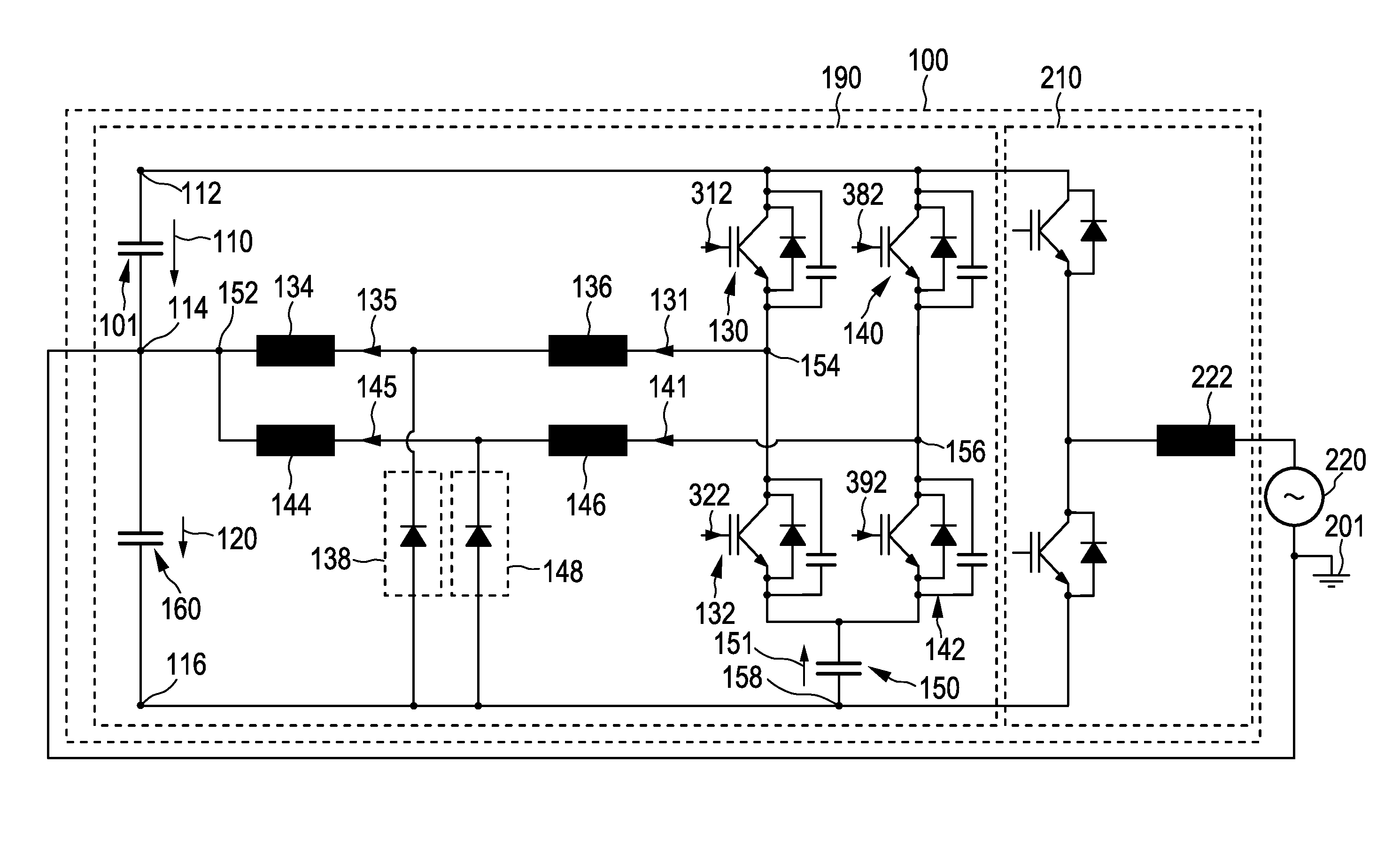
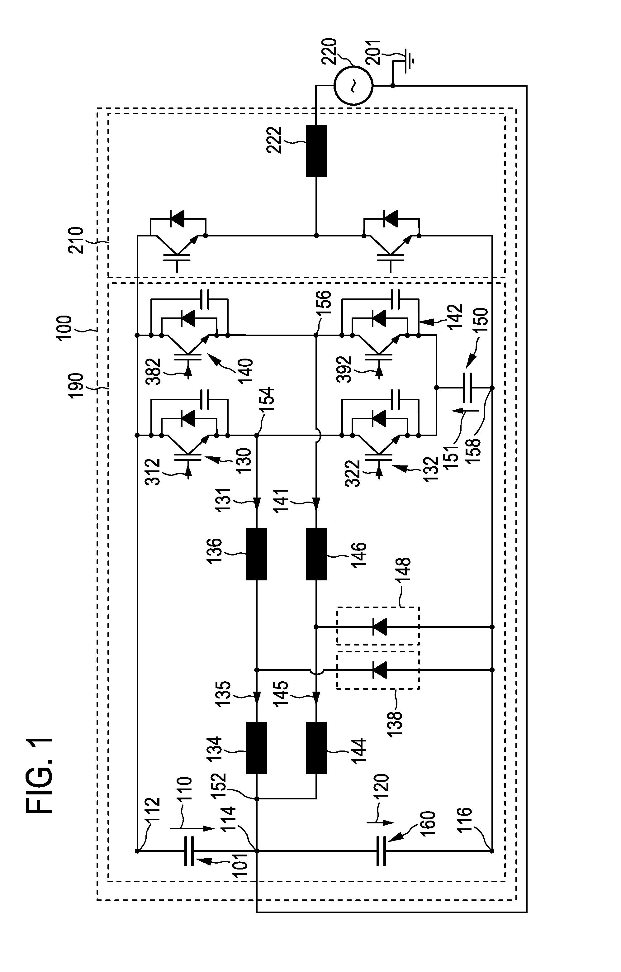
[0113]FIG. 1 shows schematically and exemplarily a representation of a circuit topology 100 of a power stage of the electrical energy conversion circuit device comprising a single phase inverter 210 in accordance with the first aspect of the invention. The circuit device 100 comprises the positive contact 112 and the common contact 114 of constant potential for receiving the direct input voltage 110.

[0114]The direct input voltage 110 may be supplied by any appropriate source (not shown in FIG. 1), for example by a fuel cell, by a rectifier connected upstream of the circuit device, a battery, or any generator of a direct voltage. In one embodiment, the direct input voltage 110 is supplied by a photovoltaic module. In most cases, there is connected an input capacitor 101 between the positive contact 112 and the common contact 114. The input capacitor 101 may either come as an external capacitor connected between the source and the circuit device or alternatively as an integrated outpu...


PUM


Abstract

The present invention is related to an electrical energy conversion circuit device (190), a method (600) of operating an electrical energy conversion circuit device, an electrical apparatus (500) and a computer program. The circuit device (190) allows earth connection and comprises two parallel connected buck-boost converters for converting a direct input voltage (110) into a direct output voltage (120). The converters are adapted to generate two phase-shifted currents (131, 141) that are received by an output capacitor (160). Due to the phase-shift, a current ripple is reduced. The direct output voltage (120) and the direct input voltage (110) preferentially have a common potential (114) and are of opposite polarities. Therefore, a second voltage of high magnitude, the sum of the direct input voltage (110) and the direct output voltage (120) is also provided.

Description

FIELD OF THE INVENTION[0001]The invention relates to an electrical energy conversion circuit device, an electrical apparatus, a method of operating an electrical energy conversion circuit device and a computer program. In particular, the invention relates to converting electrical energy provided by a photovoltaic module.BACKGROUND OF THE INVENTION[0002]United States Patent Application Publication US 2008 / 0266919 A1 discloses a circuit apparatus for a transformerless conversion of an electric direct voltage into an alternating voltage. The circuit apparatus comprises two buck-boost choppers, wherein a second buck-boost chopper is connected downstream of a first buck-boost chopper. The first of the two buck-boost choppers is adapted to convert an input voltage provided by a first electrical energy source, such as a photovoltaic module, into a first intermediate direct voltage. A second of the two buck-boost choppers is adapted to convert the first intermediate direct voltage into a se...

Claims


Application Information

Patent Timeline
Patent Type & Authority Applications(United States)
IPC IPC(8): H02M7/537H02M3/158
CPCH02M7/217H02M3/1584H02M3/158
Inventor BOEKE, ULRICH
Owner KONINKLIJKE PHILIPS ELECTRONICS NV
Features
  • Generate Ideas
  • Intellectual Property
  • Life Sciences
  • Materials
  • Tech Scout
  • Unparalleled Data Quality
  • Higher Quality Content
  • 60% Fewer Hallucinations
Learn More