Combined laser and imaging scanner

Inactive Publication Date: 2012-06-28
NCR CORP
View PDF6 Cites 5 Cited by
  • Summary
  • Abstract
  • Description
  • Claims
  • Application Information

AI Technical Summary

Benefits of technology

[0014]This allows cashier side reading of barcodes on items as well as reducing retro-reflections of the LED light off of the window back into the image capture device which may “blind” the imager.
[0015]Also, the alignment of the light source with the axis of the image capture device, i.e. pointing away from the operator, prevents the light source from shining into the eyes of the operator, thereby preventing operator headaches, fatigue and possible seizures.
[0018]Such markers allow the operator to easily align the barcode to be imaged with the axis of the image capture device. This improves the quality of the captured image and thereby reduces the likelihood the incomplete or inaccurate decoding of the image of the barcode.
[0020]Such a narrow window significantly reduces the cost of manufacture of the terminal and also increases the strength of the window in the direction of passage of goods over the window.

Problems solved by technology

However, in an effort to maximize scanner performance, the bi-optic barcode scanners of retail checkout terminals have evolved over the years into rather complex devices with multiple laser light sources, collectors, detector assemblies, mirrors and electronics.
Consequently, this arrangement can result in operator eye fatigue, headaches, and even the onset of a seizure if the operator is susceptible to them.
Another issue with current combined laser and imaging scanner located in the vertical window, is that there are no means by which the operator can easily determine if the barcode is aligned to the field of view of the imaging scanner.
This makes it very difficult for the operator to align the barcode with the camera which can lead to incomplete or blurred images of the barcode and incomplete or inaccurate decoding of the image of the barcode.
The horizontal window is therefore the most expensive component in the scanner.
The vertical window imager does not allow the scanner designer the opportunity to significantly reduce the cost of the scanner since the cost of the components in the vertical window are small compared to cost of the components in the horizontal window.

Method used


Image

  • Combined laser and imaging scanner
  • Combined laser and imaging scanner
  • Combined laser and imaging scanner

Examples


Embodiment Construction

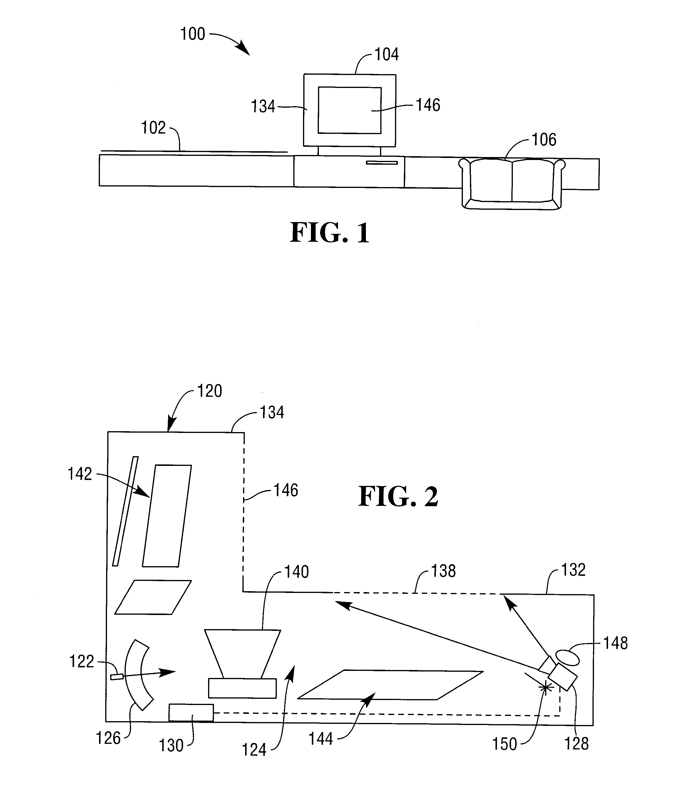
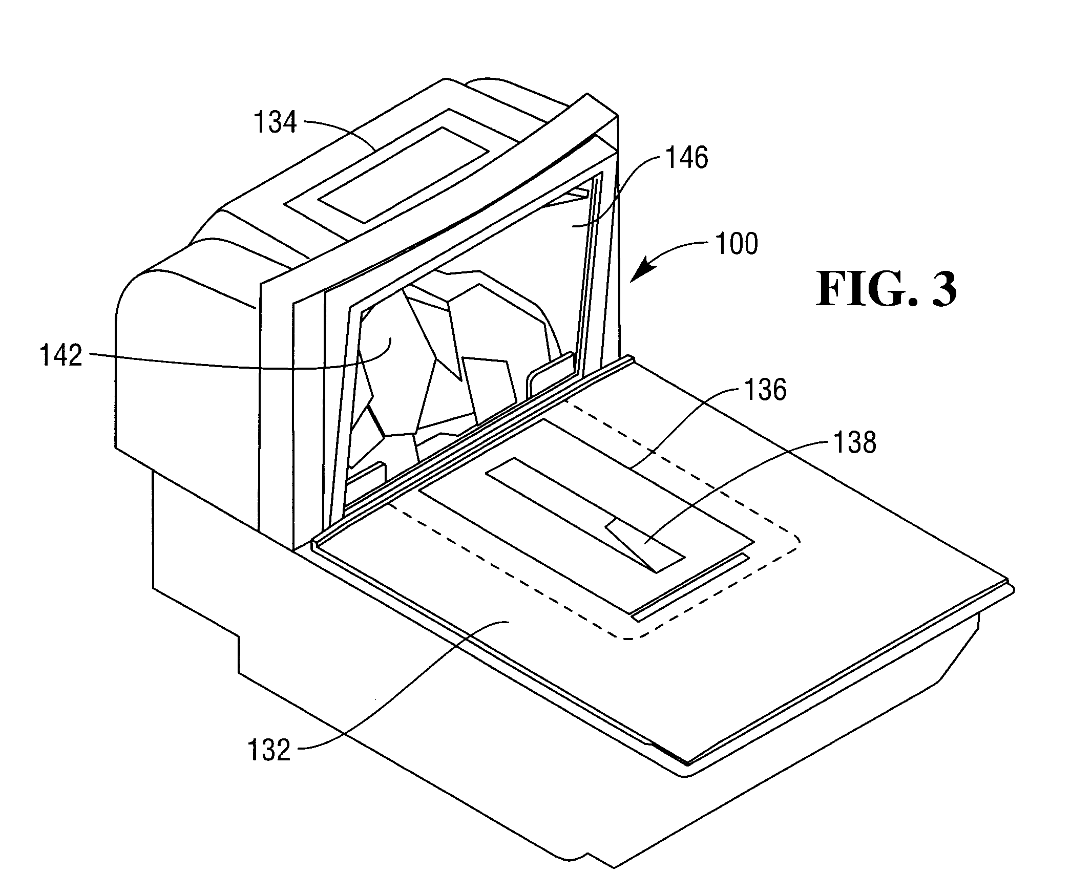
[0036]Referring now to FIGS. 1 to 3, a retail checkout terminal 100 comprises a conveyor belt drive 102, a combined barcode and image scanner 104 and a bagging area 106.

[0037]A customer places their purchased items on the belt drive 102 such that they are driven to the scanner 104 where the sales assistant scans the items and places them in the bagging area 106 for the customer to bag up.

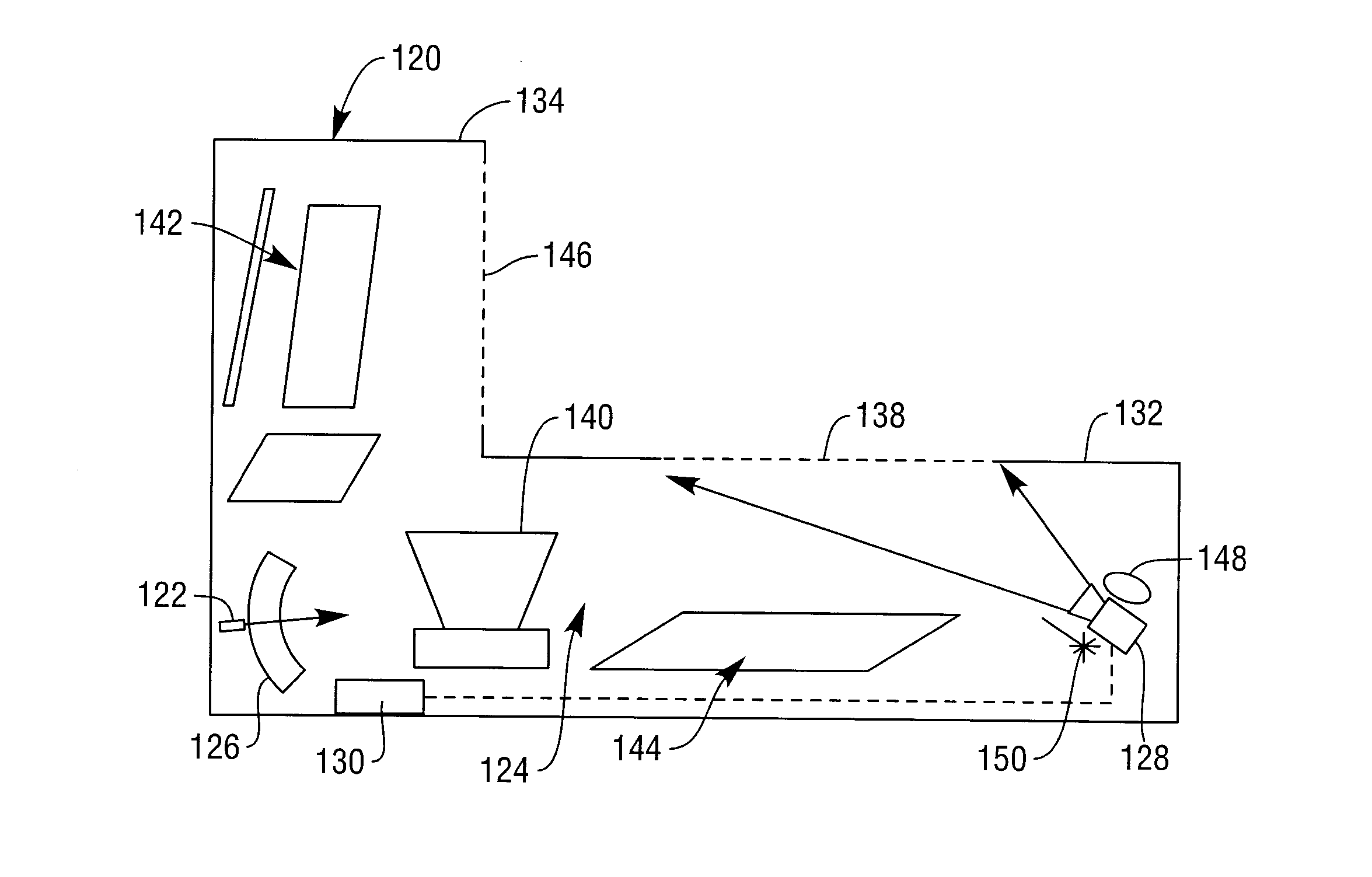
[0038]The scanner 104 comprises a housing 120, a laser light source 122, scanning optics 124, a detector 126, an image capture device 128 and a processor 130.

[0039]The housing 120 comprises a horizontal platen 132 and a vertical optics tower 134. The horizontal platen 132 comprises a weighing scale portion 136 having an elongate window 138 through it which runs perpendicular to the direction of drive of the belt drive 102. The image capture device 128, typically a CMOS imaging array or CCD camera, lies underneath the window 138 and typically has a line of sight directed to vertical optics tower 134 ...


PUM


Abstract

A combined laser and imaging scanner has an image capture device located under a horizontal platen such that the field of view of the image capture device points away from an operator side of the scanner in order to capture an image of an optical code which is being scanned by the laser scanner through the horizontal platen. The image capture device is located in amongst the mirrors which form the scanning optics of the laser scanner.

Description

FIELD OF THE INVENTION[0001]This invention relates to a combined laser and imaging scanner. In particular, but not exclusively, it relates to a hybrid bi-optic laser scanner with an imaging scanner located under a horizontal platen thereof.BACKGROUND TO THE INVENTION[0002]The original bi-optic laser scanners were typically designed to have a single laser light source along with its detector, collector and electronics located under the horizontal platen with only the mirrors required to scan in the vertical behind the vertical platen. However, in an effort to maximize scanner performance, the bi-optic barcode scanners of retail checkout terminals have evolved over the years into rather complex devices with multiple laser light sources, collectors, detector assemblies, mirrors and electronics. These components are typically located behind both horizontal and vertical platens from which the optical codes are read.[0003]In an attempt to produce a combined laser and imaging scanner a cam...

Claims


Application Information

Patent Timeline
IPC IPC(8): G06K7/14G06F17/00G07F19/00
CPCG06K7/1096G06K7/10831
Inventor HAMMER, STEVEN J.
Owner NCR CORP
Why Eureka
Try Eureka