MAW-DirectDrives

a direct drive and drive shaft technology, applied in the direction of wheel-axle combinations, electric devices, structural associations, etc., can solve the problems of significant deformation of torque produced by these power-plants, degraded efficiency, etc., and achieve the effect of reducing the requirement of storag

Inactive Publication Date: 2012-06-28
HANSEN MR DANA ALLEN
View PDF9 Cites 27 Cited by
  • Summary
  • Abstract
  • Description
  • Claims
  • Application Information

AI Technical Summary

Benefits of technology

[0015]MAW-DirectDrives offer a new opportunity to incorporate frameless direct drive technological goods on the market today into a mechanical direct drive mounting apparatus to create an ability to actuate and stop motion while at the same time utilize that motion to generate electricity to input back into the power supply thus reducing the requirement of storage or production needed to induce said motion.
[0016]MAW-DirectDrives incorporate two facing prefabricated frameless direct drive permanent magnets stators as actuators interacting with a cylindrical two-sided permanent magnets drive-rotor between said stators to induce rotation of said drive-rotor affixed to a drive-plate and spindle sub-assembly about a stationary sub-assembly's cylindrical wheel-hub projecting in from its mounting-plate supporting said stators on attached enhanced cooling stator mounting backs. They actuate and stop motion with more power while simultaneously generating electricity and connect directly inside transportation vehicle wheels and to their suspensions eliminating any need of inefficient central power-plant formats with all their associated mechanical devices.
[0017]MAW-DirectDrives configured state gain redundancy through the incorporation of the second stator and increase the output efficiency of each stator by working upon each other in a manner that becomes complementary.

Problems solved by technology

With these systems the efficiency is degraded every time the power / torque encounters friction, alteration, a change in direction or delay and when compounded with the torque originating from a rapid small diameter, possessing characteristics that require extensive processing and the use of these assemblies and mechanical devices, the torque produced by these power-plants in the end has degraded significantly and made the vehicle inefficient.
Present Hybrid technology is attempting to reduce the number of parts associated with the drive-train and eliminate the losses associated with those parts, but the torque being produced is still originating from a rapid small diameter and requires that processing and transmission, ultimately making the vehicle inefficient.
There are a few companies like e-traction in the Netherlands producing vehicles (buses and delivery trucks) that utilize a direct drive format where the electrical motor connects directly to the wheel eliminating the losses associated with a centralized power production format and they also realize the value that diameter plays in the production of torque ultimately eliminating the need for gearing but they have limited their torque production ability and efficiency with their designs inability to grow in diameter.
All Electric, Hybrid and Direct Drive technologies today understand Electronic braking and its ability to stop a vehicle but do not utilize that because of heat build-up and efficiency loss while at the same time they do not fully utilize regenerative braking technology during the braking process to assist in decreasing the on-board demand for electrical storage or production.
With today's rail transportation format being the architect of Hybrid technology, they and commercial trucking still resort to a central / core power-plant, causing to rotate a limited number of wheels to pull a heavy load that on the most part is supported on its own wheels just bearing the load and offering no assistance / help.

Method used


Image

  • MAW-DirectDrives
  • MAW-DirectDrives
  • MAW-DirectDrives

Examples


Embodiment Construction

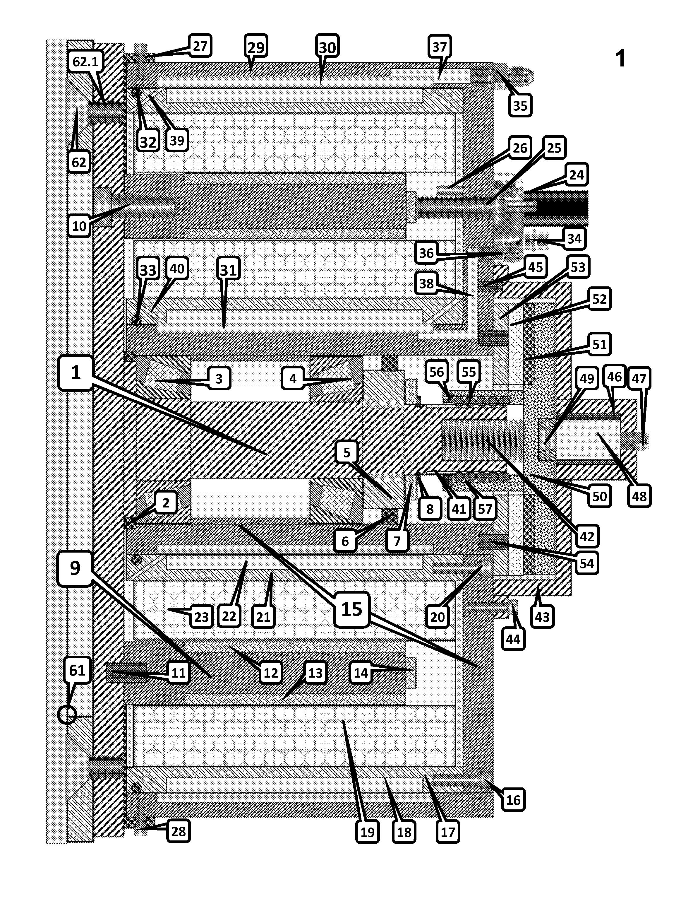
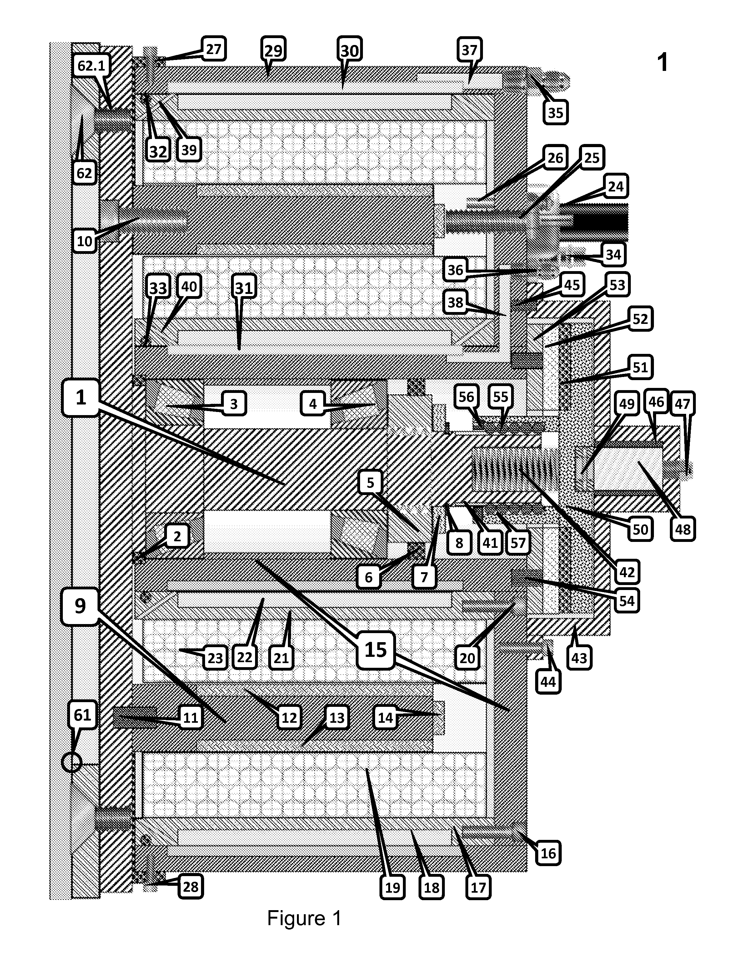
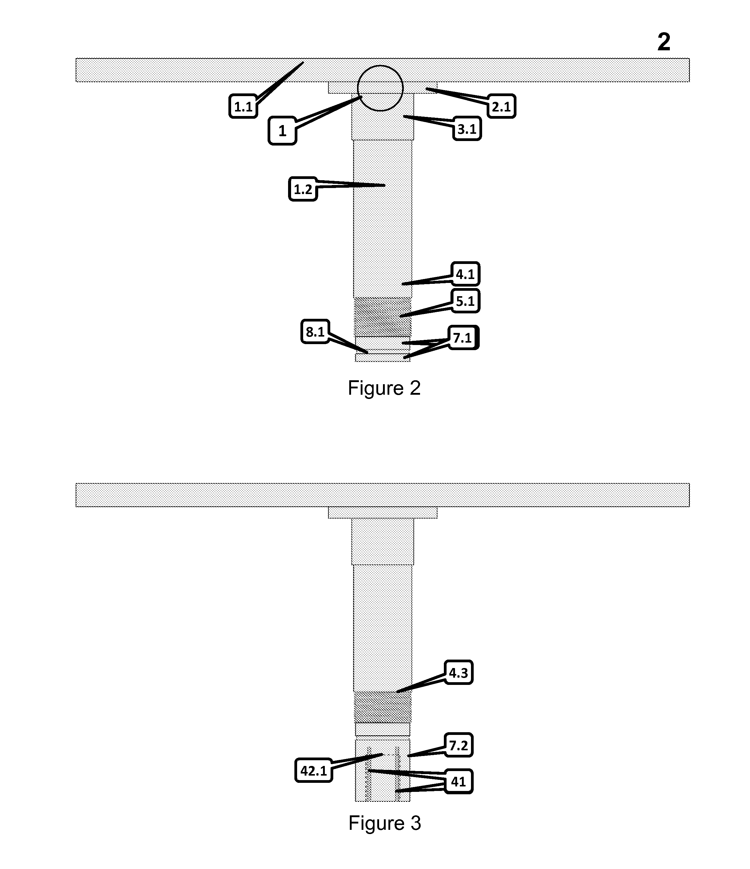
[0049]Before the various embodiments of MAW-DirectDrives are explained in detail, it is to be understood that MAW-DirectDrives are not limited in its application to the details of construction and the arrangements of components set forth in the following description or illustrated in the drawings. MAW-DirectDrives are capable of other embodiments and of being practiced or of being carried out in various ways. Also, it is to be understood that phraseology and terminology used herein with reference to device or element orientation (such as, for example, terms like “front”, “back”, “up”, “down”, “top”, “bottom”, and the like) are only used to simplify description of MAW-DirectDrives, and do not alone indicate or imply that the device or element referred to must have a particular orientation. In addition, terms such as “first”, “second”, and “third” are used herein and in the appended claims for purposes of description and are not intended to indicate or imply relative importance or sig...


PUM


Abstract

MAW-DirectDrives are a mechanical direct drive mounting apparatus incorporating paired prefabricated frameless direct drive permanent magnets brushless motor stators as actuators. The stators mount on enhanced cooling stator mounting backs connected to a stationary sub-assembly mounting-plate that support vehicle suspensions on its rear. A drive-plate and spindle sub-assembly connected inside vehicle wheels fastens the two sub-assemblies and holds a cylindrical two-sided permanent magnets drive-rotor concentrically disposed between the stators and proximate to the stators' core peripheral surfaces to interact and actuate rotation about the stationary sub-assembly's cylindrical wheel-hub. The paired facing stators interacting with the drive-rotor create a complementary working relationship affording greater efficiency and power plus gains dual functionality by utilizing actuated rotation to generate electricity via the second stator for input back into the power supply reducing the vehicle's need of electrical power. Stationary sub-assembly mounted supplemental air brake units utilize lengthened spindles projecting out for brake-rotor operation.

Description

CROSS-REFERENCE TO RELATED APPLICATIONS[0001]Applicant states that this application is a continuation-in-part of application Ser. No. 12 / 386,047, filed Apr. 13, 2009 which claims the benefit of U.S. Provisional Patent Application No. 61 / 124,179 filed Apr. 15, 2008 and that said applications are incorporated by reference herein in their entirety.STATEMENT REGARDING FEDERALLY SPONSORED RESEARCH OR DEVELOPMENT[0002]Not ApplicableREFERENCE TO SEQUENCE LISTING, A TABLE, OR A COMPUTER PROGRAM LISTING COMPACT DISC APPENDIX[0003]Not ApplicableBACKGROUND OF THE INVENTION[0004]1. Field of the Invention[0005]The present invention also known as MAW-DirectDrives henceforth will be referenced by said term.[0006]MAW-DirectDrives relate to a mechanical direct drive mounting apparatus that enables incorporating paired prefabricated frameless direct drive permanent magnets brushless motor stators as actuators, to create a dual functioning direct drive motor capable of actuating rotation of a connecte...

Claims


Application Information

Patent Timeline
Patent Type & Authority Applications(United States)
IPC IPC(8): B60K7/00
CPCB60K7/0007F16D2121/04B60K2007/0038B60K2007/0092F16D55/00H02K5/20H02K7/102H02K7/14H02K7/1846H02K9/00H02K9/19H02K11/0047H02K16/04H02K29/08H02K49/06H02K2213/03B60K2007/003B60L7/04B60L2200/18B60L2200/36B60L2220/16H02K11/25Y02T10/64H02K5/207H02K5/203
Inventor HANSEN, DANA ALLEN
Owner HANSEN MR DANA ALLEN
Why Eureka
Try Eureka