Wireless power feeder, wireless power receiver, and wireless power transmission system

a technology of wireless power receiver and wireless power feeder, which is applied in the direction of transformer/inductance circuit, basic electric elements, inductance, etc., can solve problems such as risk of malfunction, and achieve the effects of preventing malfunction, and accurately detecting the magnetic field of the power receive coil

Active Publication Date: 2012-06-28
TDK CORPARATION
View PDF3 Cites 29 Cited by
  • Summary
  • Abstract
  • Description
  • Claims
  • Application Information

AI Technical Summary

Benefits of technology

[0024]Furthermore, in this wireless power feeder, the outer shape of the magnetic detection element in the resonance current detector is smaller than the winding region of the power feed coil, and this magnetic detection element is disposed in such a manner that the magnetic detection direction thereof forms an angle of not less than 80° and not more than 100° with respect to the magnetic field vectors (lines of magnetic force) generated by the power feed coil. Accordingly, the resonance current detector is able to detect the magnetic field of the power receive coil accurately, without detecting the magnetic field of the power feed coil.
[0025]The wireless power receiver according to the present invention is a wireless power receiver which acquires power by a non-contact method from the wireless power feeder described above, comprising a power receive resonance circuit including a power receive coil and a power receive capacitor, the wireless power receiver acquiring power from the power feed coil by the power receive coil on the basis of a magnetic field resonance effect between the power feed coil in the wireless power feeder and the power receive coil in the wireless power receiver.
[0026]According to this wireless power receiver, power is acquired by a non-contact method from the wireless power feeder described above, and therefore it is possible to prevent malfunction when performing co...

Problems solved by technology

Consequently, in a wireless power transmission system of this kind, there is a risk of malfunct...

Method used


Image

  • Wireless power feeder, wireless power receiver, and wireless power transmission system
  • Wireless power feeder, wireless power receiver, and wireless power transmission system
  • Wireless power feeder, wireless power receiver, and wireless power transmission system

Examples


first embodiment

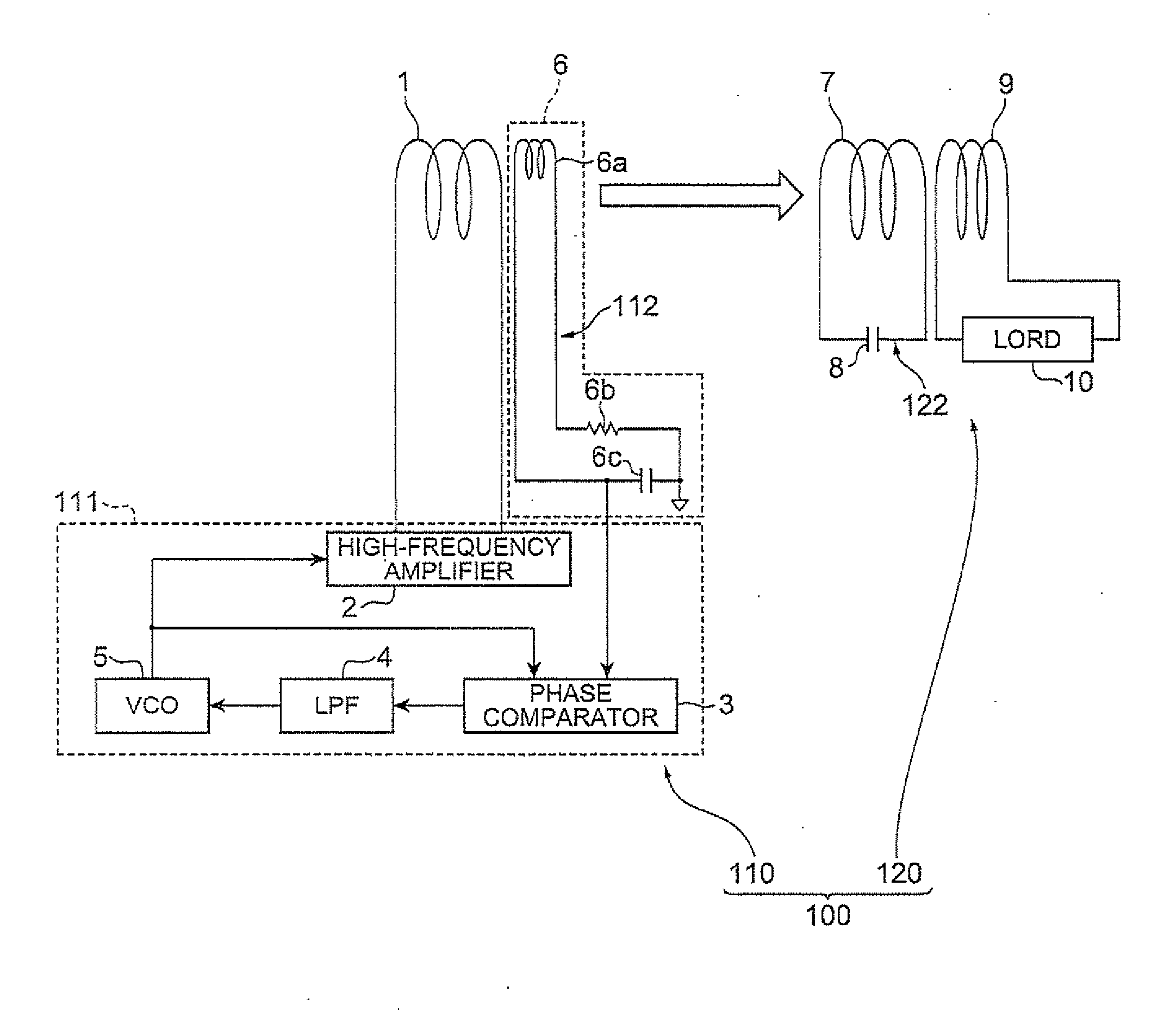
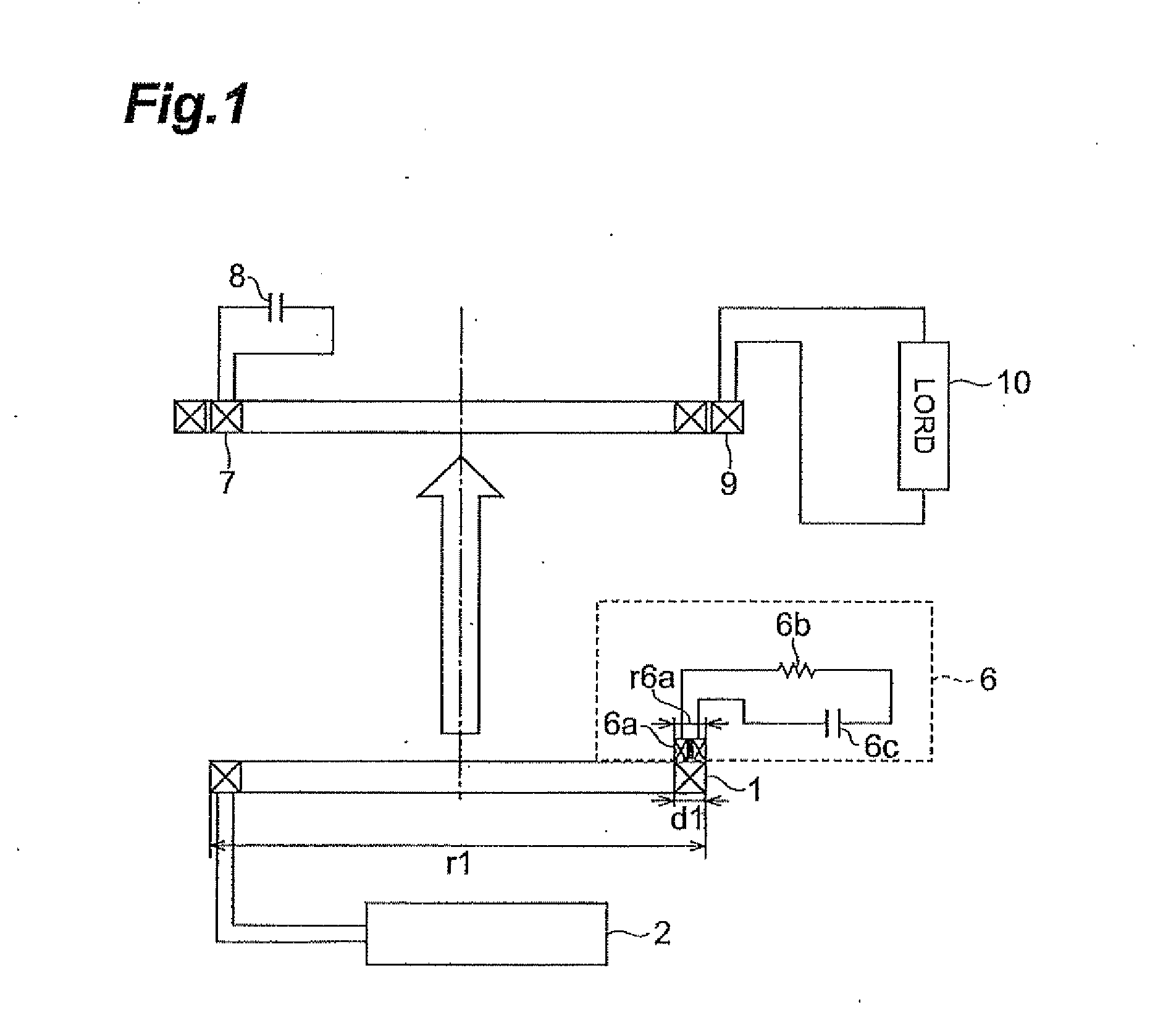
[0048]FIG. 3 is a diagram showing the electrical composition of a wireless power transmission system relating to a first embodiment of the present invention. The wireless power transmission system 100 shown in FIG. 3 comprises a wireless power feeder 110 and a wireless power receiver 120, and performs power transmission by a non-contact method from the wireless power feeder 110 to the wireless power receiver 120.

[0049]The wireless power feeder 110 comprises a power feed coil 1, a resonance current detector 6, and a control circuit 111. On the other hand, the wireless power receiver 120 comprises a power receive resonance circuit 122 comprising a power receive coil 7 and a power receive capacitor 8.

[0050]In the wireless power feeder 110, the control circuit 111 supplies an AC current (for example, a square wave or sinusoidal wave current) to the power feed coil 1, whereby power is supplied from the power feed coil 1 to the power receive coil 7 on the basis of a magnetic field resonan...

second embodiment

[0076]FIG. 4 is a diagram showing the electrical composition of a wireless power feeder 110A relating to a second embodiment of the present invention. In this way, the wireless power transmission system 100 may comprise a wireless power feeder 110A instead of the wireless power feeder 110.

[0077]The wireless power feeder 110A differs from the first embodiment in that a resonance current detector 6A is provided instead of the resonance current detector 6 in the wireless power feeder 110. The rest of the composition of the wireless power feeder 110A is the same as the wireless power feeder 110.

[0078]The resonance current detector 6A comprises a Hall element (magnetic detection element, magnetic sensor) 6d, a current source 6e, an operating amplifier 6f and resistance elements R1 and R2, instead of the detection resonance circuit 112 which is constituted by the detection coil 6a, the detection resistance element 6b and the detection capacitor 6c, in the resonance current detector 6.

[007...

third embodiment

[0085]FIG. 11 is a diagram showing the electrical composition of a wireless power feeder 110B relating to a third embodiment of the present invention. In this way, the wireless power transmission system 100 may comprise a wireless power feeder 110B instead of the wireless power feeder 110.

[0086]The wireless power feeder 110B differs from the first embodiment in that four resonance current detectors 6 are provided, together with an adder 11, instead of the resonance current detector 6 in the wireless power feeder 110. The adder 11 adds up the voltages at either end of the detection capacitors 6c in the four resonance current detectors 6, and outputs the result to the phase comparator 3. The rest of the composition of the wireless power feeder 110B is the same as the wireless power feeder 110.

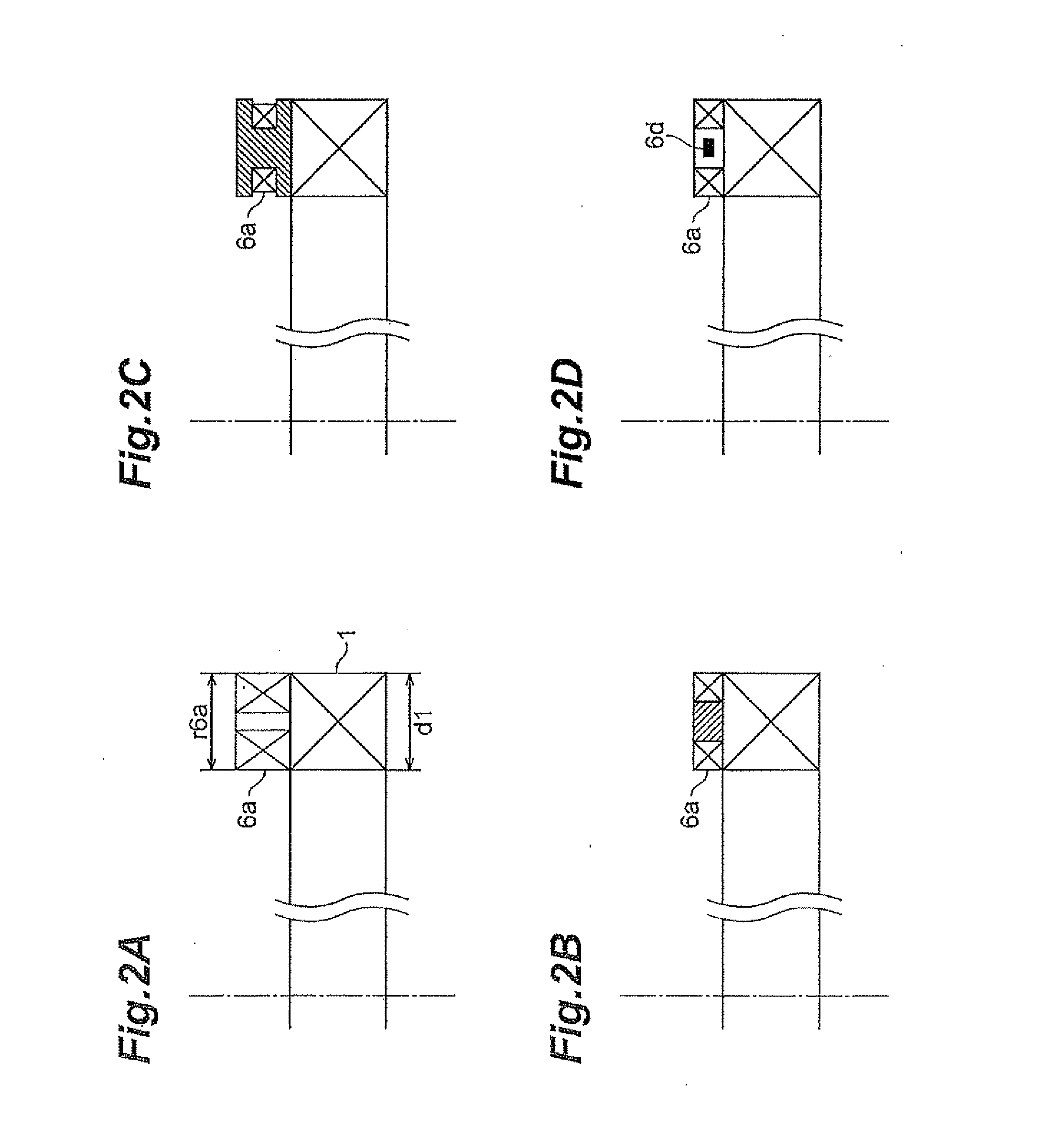
[0087]FIG. 10A is a diagram showing an arrangement of the detection coils 6a in the four resonance current detectors 6 with respect to the power feed coil 1, as viewed from the side of the power ...


PUM


Abstract

A wireless power feeder which performs power feed to a wireless power receiver having a power receive resonance circuit including a power receive coil and a power receive capacitor, this wireless power feeder including: a power feed coil; a resonance current detector; and a control circuit; wherein the power feed coil does not substantially constitute a resonance circuit; the current detector has a detection resonance circuit including a detection coil and a detection capacitor, and detects a resonance current of the power receive resonance circuit; the winding region of the detection coil in the current detector is smaller than the winding region of the power feed coil; and the detection coil in the current detector is disposed such that the central winding axis thereof forms an angle of not less than 80° and not more than 100° with respect to magnetic field vectors generated by the power feed coil.

Description

CROSS REFERENCE TO RELATED APPLICATION[0001]This application claims priority to U.S. Provisional Application No. 61 / 427,607 filed on Dec. 28, 2010 by the same Applicant, which is hereby incorporated by reference in its entirety.BACKGROUND OF THE INVENTION[0002]1. Field of the Invention[0003]The present invention relates to a wireless power feeder, a wireless power receiver, and a wireless power transmission system for transmitting power by a non-contact method.[0004]2. Related Background Art[0005]Japanese Patent Application Publication No. 2010-166693 discloses a wireless power transmission system which transmits power by a non-contact (wireless) method from a wireless power feeder to a wireless power receiver. In this wireless power transmission system, power is transmitted by using an electromagnetic induction effect. Therefore, the wireless power feeder 10 comprises a power feed resonance circuit having a power feed coil 14 and a power feed capacitor 15, and furthermore, the wire...

Claims


Application Information

Patent Timeline
IPC IPC(8): H02J17/00
CPCH02J17/00H02J50/12H02J50/90H02J50/80
Inventor URANO, TAKASHI
Owner TDK CORPARATION
Why Eureka
Try Eureka