Superconducting rotating electrical machine and stator for use with superconducting rotating electrical machine

a superconducting rotating electrical machine and stator technology, applied in synchronous machines, windings, dynamo-electric components, etc., can solve the problems of large copper loss, insufficient effective reduction of temperature increase, electric resistance heating, etc., to achieve the effect of improving power conversion efficiency

Active Publication Date: 2012-06-28
KAWASAKI HEAVY IND LTD
View PDF11 Cites 41 Cited by
  • Summary
  • Abstract
  • Description
  • Claims
  • Application Information

AI Technical Summary

Benefits of technology

[0022]According to the invention, an improved power conversion efficiency is attained in the superconducting rotating electrical machine with a superconducting rotor and normal-conducting stator.

Problems solved by technology

For example, the copper loss results in an electric resistance heating due to electric current which flows in the conductive members such as armature or stator windings.
In particular, the copper loss occupies a large part of the total loss in the rotating devices such as small- or medium-size, brushless rotating devices or permanent magnet synchronous generators.
The eddy loss results in the electric resistance heating due to the eddy current generated around the magnetic flux, which is in proportion to the square of the driving frequency of the rotating device.
Typically, a ratio of the gross cross-sectional area of the windings relative to the total cross-sectional area of the slot in the normal-conducting rotating electrical machine ranges from about 30% to about 40%, which is insufficient for effectively reducing a temperature increase due to the copper loss in the stator if a large amount of electric current is applied to the windings.
Further, using stator windings made of bismuth-based high temperature superconducting wires typically employed in the superconducting rotating electrical machine may affect the superconducting property such as an increase in temperature of the windings due to heat generated by the alternating-current loss and a resultant decrease in critical current.
Then, providing a superconducting property for the stator may be technically difficult and, even if possible, result in a cost increase in the manufacturing of the superconducting rotating electrical machine.
Also, forming the stator windings of the superconducting rotating electrical machine with bismuth-based high temperature superconducting material conventionally used in the superconducting rotating electrical machine results in the temperature increase in the windings due to alternating-current loss and thereby reduces the critical current associated with the superconducting property of the windings.
In conclusion, it may be technically impossible to provide a superconducting property for the stator.
Also, providing a superconducting property for the stator will result in a cost increase in the manufacturing of the superconducting rotating electrical machine.
In the meantime, a superconducting rotating electrical machine with a superconducting rotor and a normal-conductive stator can increase the intensity of magnetic field and, as a result, decrease the overall manufacturing cost of the superconducting rotating electrical machine, which reduces copper loss in the superconducting rotor and, as a result, increases the power conversion efficiency, but increases copper loss, iron loss, or eddy current loss in the normal-conductive stator.
This results in that the elevated efficiency derived from the superconducting rotor is cancelled by the losses in the stator, which fails to meet the requirements for the further increase of power conversion efficiency in the superconducting rotating electrical machine.
As a tradeoff, however, the normal-conductive property in the stator causes copper loss, iron loss, and / or eddy current loss.
Also, the magnetic field of the iron core will be instantly saturated by the magnetic filed of the armature, which weakens the alternating magnetic field.

Method used


Image

  • Superconducting rotating electrical machine and stator for use with superconducting rotating electrical machine
  • Superconducting rotating electrical machine and stator for use with superconducting rotating electrical machine
  • Superconducting rotating electrical machine and stator for use with superconducting rotating electrical machine

Examples


first embodiment

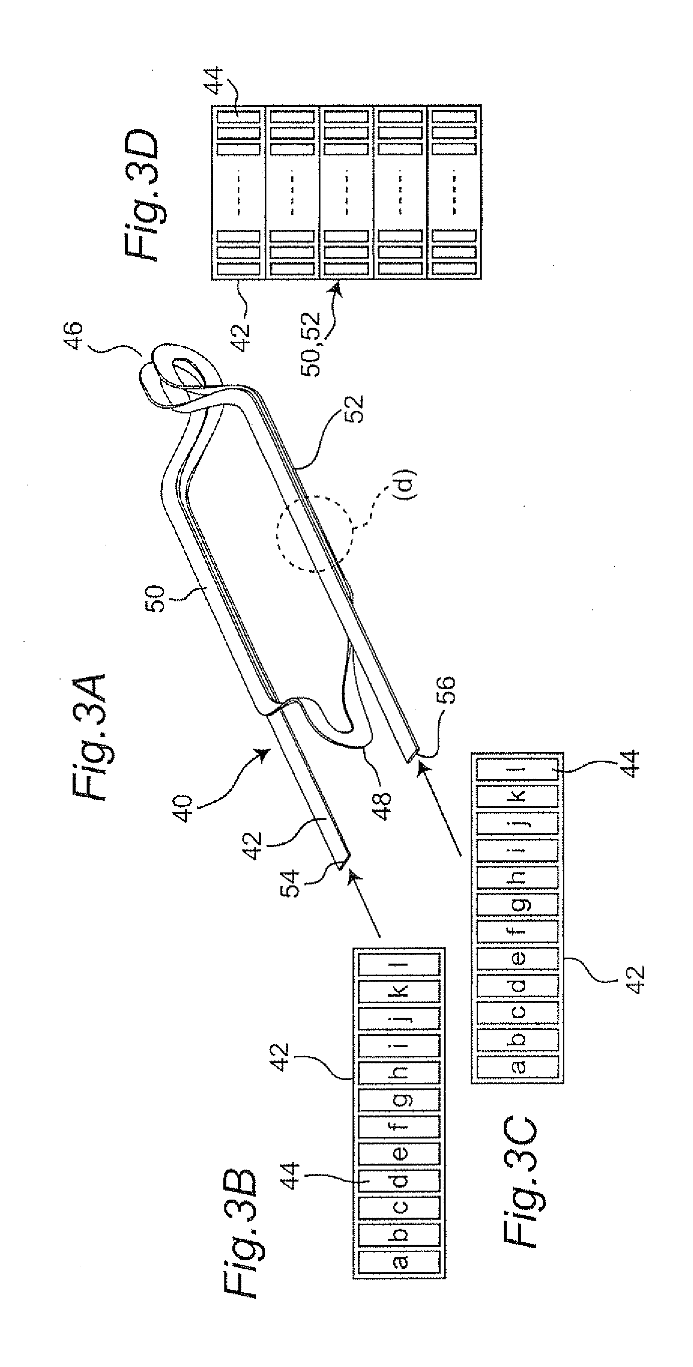
[0057]To address this problem, in the first embodiment shown in FIGS. 10A, 10B and 10C, each of the electrical connections between the neighborhood windings, e.g., windings 40(1) and 40(2), windings 40(2) and 40(3), and windings 40(3) and 40(4) (hereinafter referred to as “coil-to-coil connection”), is performed by connecting the distal ends 54 of wires 44(a)-44(l) with the neighborhood proximal ends 56 of wires 44(1)-44(a), respectively, namely, wires 44(a) and 44(l), 44(b) and 44(k), . . . , 44(k) and 44(b), and 44(l) and 44(a) are connected with each other. This results in that, as shown in FIG. 11, most of the eddy currents generated in the proximal straight portions 50 and the distal straight portions 52, flowing in the opposite directions in the winding are cancelled by each other. Then, the eddy current in the winding is minimized.

second embodiment

[0058]It should be noted that the windings are arranged at a regular interval in the peripheral direction and, therefore, as shown in FIGS. 12A and 12B, a certain phase difference exists between one eddy current in one winding and the other eddy current in the neighborhood winding, so that not all the eddy currents are cancelled by each other and a small amount of eddy current remains in each winding. To address this problem, in the second embodiment shown in FIGS. 13A, 13B and 13C, a connection between one winding group 72(1) including windings 40(1)-40(4) and arranged to oppose one magnetic pole and the other winding group 72(2) including windings 40(25)-40(28) and arranged to oppose the other magnetic pole, the first and second groups being spaced 180 degrees away from each other in the peripheral direction (herein after referred to as “pole-to-pole connection”), is performed by connecting the distal ends of the wires 44(a)-44(l) in the first group 72(1) with the proximal ends of...


PUM


Abstract

A superconducting rotating electrical machine has a rotor with superconducting windings and a stator disposed around the rotor. The stator has a number of teeth disposed at a regular interval about a rotational axis of the rotor to define slots each between adjacent teeth and a plurality of windings, each winding having a strip-like wire member, the wire member having a plurality of rectangular cross-section wires in which said rectangular wires are arranged in parallel to each other and electrically insulated away from each other, the winding being constructed by winding the strip-like wire member a plurality of times to have first and second winding portions having a cross section in which the rectangular wires are positioned in matrix.

Description

FIELD OF THE INVENTION[0001]The present invention relates to a superconducting rotating electrical machine and a stator for use with the rotating electrical machine. In particular, the present invention relates to a stator capable of increasing a power conversion efficiency of the rotating electrical machine.BACKGROUND OF THE INVENTION[0002]Conventionally, a variety of rotating electrical machines such as induction motor and permanent-magnetic synchronous motor have been proposed for use with rotating electrical machines or power generators. Typically, each rotating electrical machine has windings and a core so that magnetic fluxes generated by an application of electric current to the windings are concentrated in the core to increase the intensity of magnetic field and a resultant rotational force of the rotating electrical machine.[0003]For this purpose, the core is made of ferromagnetic material such as iron and has slots or grooves defined therein for accommodation of the windin...

Claims


Application Information

Patent Timeline
Patent Type & Authority Applications(United States)
IPC IPC(8): H02K3/28H02K3/12
CPCH02K3/28Y02E40/625H02K55/04H02K3/47Y02E40/60
Inventor UMEMOTO, KATSUYAAIZAWA, KIYOSHIYOKOYAMA, MINORUKIMURA, YOUSUKE
Owner KAWASAKI HEAVY IND LTD
Why Eureka
Try Eureka