Central lc pll with injection locked ring pll or dell per lane

Inactive Publication Date: 2012-06-28
STMICROELECTRONICS CANADA
View PDF11 Cites 12 Cited by
  • Summary
  • Abstract
  • Description
  • Claims
  • Application Information

AI Technical Summary

Problems solved by technology

However, it is not possible to simultaneously provide various data rates for each lane independent of other lanes, and it takes extra power for the clock bus to span the entire lane width rather than just the essential portion where connections are needed.
Most or many high data-rate SerDes have the problems described above, and usually resort to diminished capability or incre

Method used


Image

  • Central lc pll with injection locked ring pll or dell per lane
  • Central lc pll with injection locked ring pll or dell per lane
  • Central lc pll with injection locked ring pll or dell per lane

Examples


Embodiment Construction

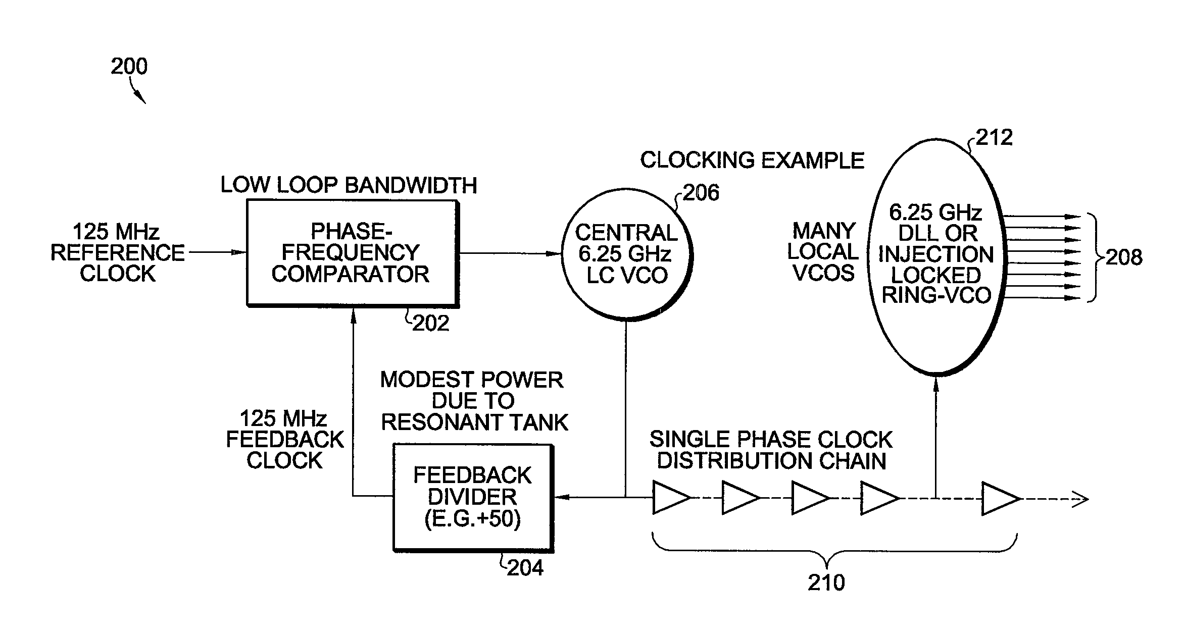
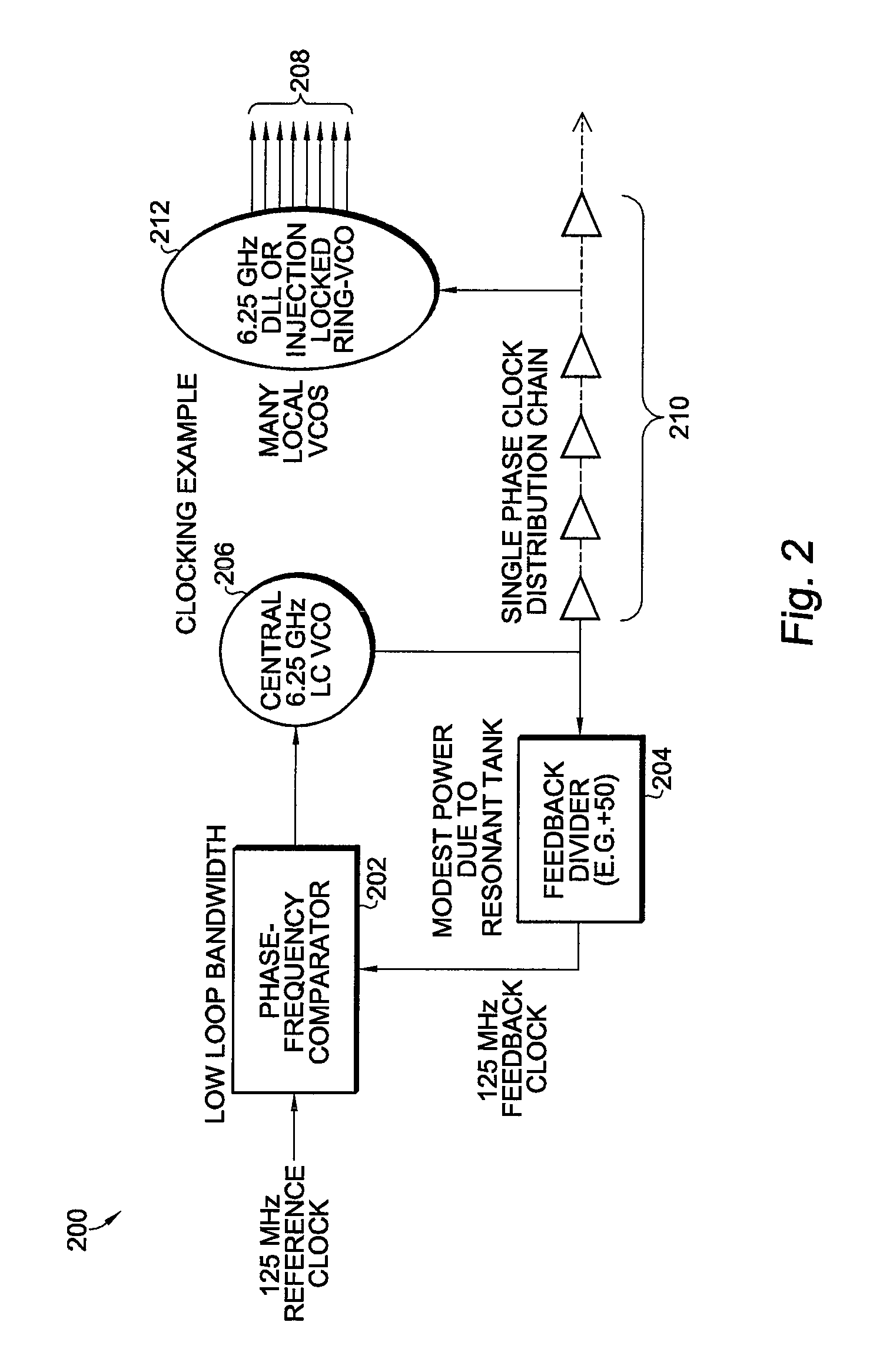
[0015]A clocking circuit according to the present invention solves the problem of implementing ASIC circuit blocks requiring many multiphase, low-noise, low-power clock sources, each independently able to operate at one of multiple centrally regulated frequencies. One primary application is for implementing many SerDes lanes in a single ASIC.

[0016]An improved SerDes clocking strategy according to the present invention includes the following elements:

[0017]LC VCOs have high passive EM energy storage and low gain, hence, low phase-noise;

[0018]Low phase-noise can be achieved even with low LC PLL loop bandwidth, which helps to also reduce Reference Clock phase-noise transfer to outputs;

[0019]The high bandwidth of injection locking transfers the low LC noise to the range VCOs; and

[0020]Single-phase distribution reduces power and area and allows per-lane rate choices.

[0021]Referring now to FIG. 2, clocking circuit 200 according to an embodiment of the invention includes a 125 MHz referenc...


PUM


Abstract

A clock circuit includes a frequency or phase comparator for receiving a reference clock signal, an LC VCO coupled to the comparator, a feedback divider coupled between the LC VCO and the comparator, a clock distribution chain coupled to the feedback divider and the first VCO, and a DLL or injection-locked ring-VCO coupled to the clock distribution chain for providing a plurality of phased output clock signals.

Description

RELATED APPLICATION[0001]The present invention claims priority from U.S. Provisional Patent Application Ser. No. 61 / 427,635 filed Dec. 28, 2010, and is incorporated herein by reference in its entirety for all purposes as if fully set forth herein.BACKGROUND OF THE INVENTION[0002]The present invention relates to clock circuits, and more particularly clock circuit used with Serializer / Deserializer (SerDes) circuits.[0003]High data-rate SerDes circuits often use a multi-phase clock source to allow phase to be accurately and rapidly manipulated by digital means when needed, while otherwise maintaining very low phase noise. One way this can be achieved is by using a common, central, low noise, multi-phase clock source to divide the relatively large clock power needed to achieve low phase noise, over many lanes. However, it is not possible to simultaneously provide various data rates for each lane independent of other lanes, and it takes extra power for the clock bus to span the entire la...

Claims


Application Information

Patent Timeline
IPC IPC(8): H03L7/08
CPCG06F1/06H03L7/24H03L7/23
Inventor MADEIRA, PAULHOGEBOOM, JOHNHOGEBOOM-NIVERA, PAT
Owner STMICROELECTRONICS CANADA
Why Eureka
Try Eureka