Memory fastening device, computer motherboard and computer

Inactive Publication Date: 2012-06-28
FENG LIN
View PDF18 Cites 1 Cited by
  • Summary
  • Abstract
  • Description
  • Claims
  • Application Information

AI Technical Summary

Benefits of technology

[0042]Firstly, by providing the elastic insulating rubber bar at the bottom of the memory slot of the memory connection base, without changing structures of the conventional memory connection base and the conventional memory, an elastic stress exists between the memory and the memory connection base and counteracts with an impact force of the memory when the memory is being shaken so as to maint

Problems solved by technology

Computer crash, blue screen, a failure to start normally or a failure to enter the operating system after the start often occurs to a computer.
Many reasons can cause that, but one main reason is the memory failure, including a memory corruption, an incompatibility and a failure in the connection between a memory connection base and a memory.
The failure in the connection between the memory and the memory connection base is the most common memory failure in daily lives and also the factor leading to the highest maintenance cost.
Firstly, dust comes into the memory slot of the memory connection base, which results in that the connecting fingers of the memory and the elastic reeds of the memory connection base are also attached with some dust.
When the dust exists between the elastic reeds of the memory connection base and the connecting fingers of the memory, the electrical connecting performance of the memory and the memory connection base is changed so that a computer failure may occur.
A great deal of dust exists between the memory connection base and the memory so that a poor contact or a short circuit may occur.
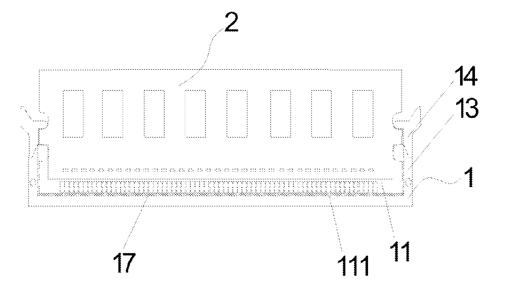
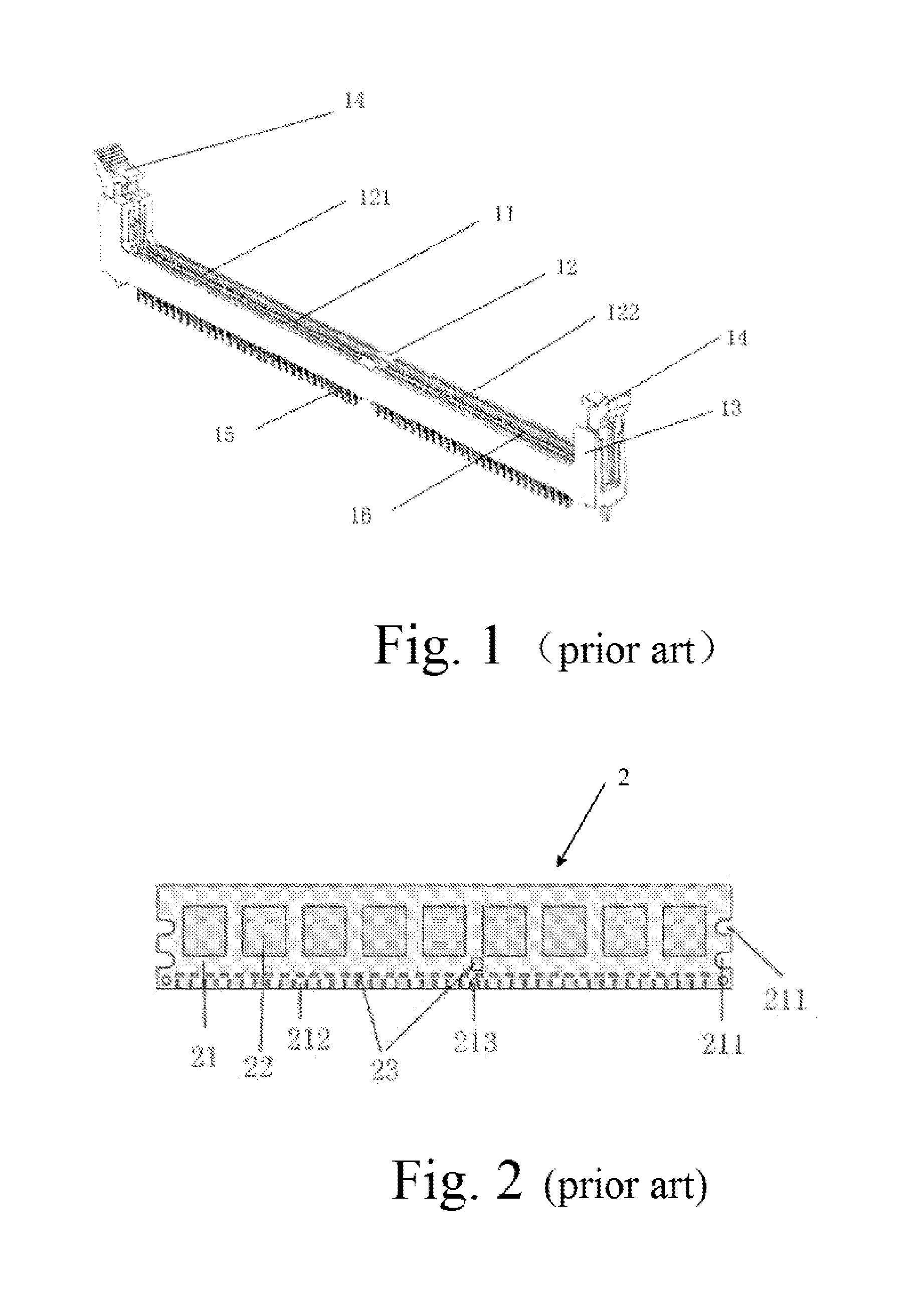
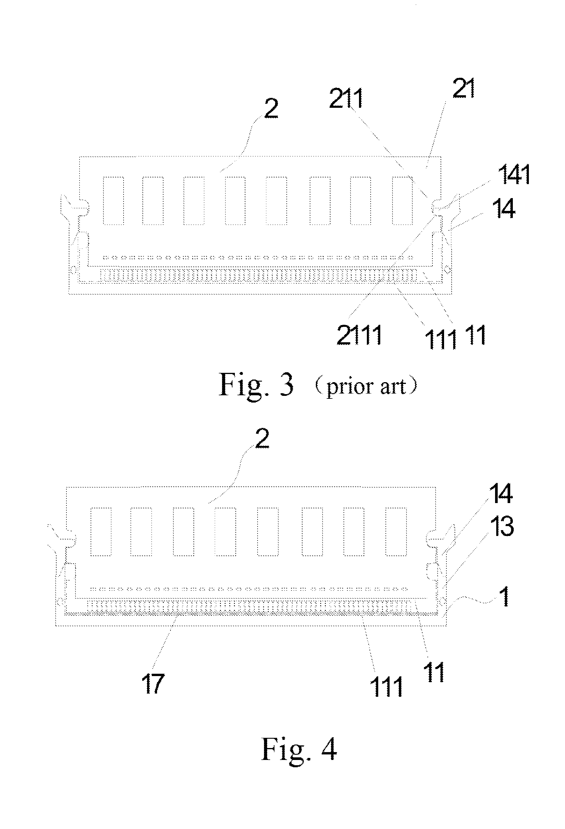
On the other hand, as shown in FIG. 1, the plurality of heat emitting holes above the perforated hole which has electricity-conducting reeds of the memory connection base provided therein are open so that dust tends to enter between the memory slot and the memory through the plurality of heat emitting holes and the perforated holes, which leads to a poor contact or a short circuit between the memory and the memory con

Method used


Image

  • Memory fastening device, computer motherboard and computer
  • Memory fastening device, computer motherboard and computer
  • Memory fastening device, computer motherboard and computer

Examples


Example

[0052]The present invention relates to a memory fastening device which is an improvement based on a conventional memory connection base. The present invention is characterized in that a purpose of fastening a memory is realized without changing conventional structures of a standardized memory connection base and a standardized memory, which has a low cost, an ideal result and a great potential on the market.

[0053]The present invention is realized by following principles.

[0054]A conventional memory is plugged into a memory slot of a memory connection base. The bayonet connector of the memory is buckled by a hook fastener to fix the memory. When installing the memory, by pressing the memory downwards with hands, the memory is plugged into the memory slot. Once a lowest end of the memory contacts with a bottom of the memory slot, the bayonet connectors of the memory are exactly buckled by the hook fastener of the memory connection base. The hook fastener resists the memory at a directi...


PUM


Abstract

A memory fastening device, a computer motherboard including the memory fastening device and a computer including the computer motherboard are provided. The memory fastening device includes a memory connection base for plugging and fixing a memory and is characterized in further comprising an elastic component which fills in a space between the memory connection base and the memory. The memory fastening device is an improvement based on a conventional memory connection base. The memory fastening device is characterized in that a purpose of fastening the memory is realized without changing conventional structures of the standardized memory connection base and the standardized memory.

Description

BACKGROUND OF THE PRESENT INVENTION[0001]1. Field of Invention[0002]The present invention relates to a field of electrical connecting structures, and more particularly to a memory fastening device, a computer motherboard having the memory fastening device and a computer having the computer motherboard.[0003]2. Description of Related Arts[0004]Computer crash, blue screen, a failure to start normally or a failure to enter the operating system after the start often occurs to a computer. Many reasons can cause that, but one main reason is the memory failure, including a memory corruption, an incompatibility and a failure in the connection between a memory connection base and a memory.[0005]The incompatibility between the memory and the motherboard is caused by the memory and the motherboard, and can be detected at the initial phase of the installment. It is easy to detect and solve the incompatibility.[0006]The failure in the connection between the memory and the memory connection base ...

Claims


Application Information

Patent Timeline
IPC IPC(8): H01R24/60
CPCG06F1/185
Inventor LIAO, YINGWENFENG, LINFENG, TIANSHENGPAN, QIAOZHENFENG, PINGFENG, AIPING
Owner FENG LIN
Why Eureka
Try Eureka