Humifidier with wireless temperature sensing

a wireless temperature sensing and humidifier technology, applied in the direction of medical devices, inhalators, other medical devices, etc., can solve the problem of inaccuracy of the temperature received by the base uni

Inactive Publication Date: 2012-07-05
KONINKLIJKE PHILIPS ELECTRONICS NV
View PDF13 Cites 23 Cited by
  • Summary
  • Abstract
  • Description
  • Claims
  • Application Information

AI Technical Summary

Benefits of technology

[0009]Another aspect of the invention provides a system for delivering a flow of gas to an airway of a user. The system includes a gas flow generator that generates a flow of gas and a user circuit coupled to the gas flow generator and adapted to communicate the flow of gas to an airway of a user. The system also includes a humidifier operatively connected to the user circuit to elevate the humidity of the gas in the user circuit to a circuit humidity level. The humidifier includes a base unit and a chamber constructed and arranged to hold a reservoir of liquid. The system further includes a sensor operatively configured to sense a condition within the chamber, the condition being a temperature of the liquid, the humidity of the gas in the chamber, and / or any other condition or parameter. The system also includes a radiation signal transmitter carried by the chamber and operatively associated with the sensor. The transmitter is arranged to send wirelessly a radiation signal indicative of the sensed condition. The system further includes a radiation signal receiver carried by the base unit and arranged to receive the radiation signal from the transmitter. The system further includes a control unit that controls the condition based at least in part on the radiation signal received by the radiation signal receiver.
[0010]These and other objects, features, and characteristics of the present invention, as well as the methods of operation and functions of the related elements of structure and the combination of parts and economies of manufacture, will become more apparent upon consideration of the following description and the appended claims with reference to the accompanying drawings, all of which form a part of this specification, wherein like reference numerals designate corresponding parts in the various figures. It is to be expressly understood, however, that the drawings are for the purpose of illustration and description only and are not intended as a definition of the limits of the invention. As used in the specification and in the claims, the singular form of “a”, “an”, and “the” include plural referents unless the context clearly dictates otherwise.

Problems solved by technology

Because the humidifier reservoir is constantly being detached from the base unit to be cleaned and refilled with liquid, there may be inaccuracies in the temperature received by the base unit due to the accumulated dirt or wear and tear of the mechanical or electrical connection between the humidifier reservoir and the base unit.

Method used


Image

  • Humifidier with wireless temperature sensing
  • Humifidier with wireless temperature sensing
  • Humifidier with wireless temperature sensing

Examples


Embodiment Construction

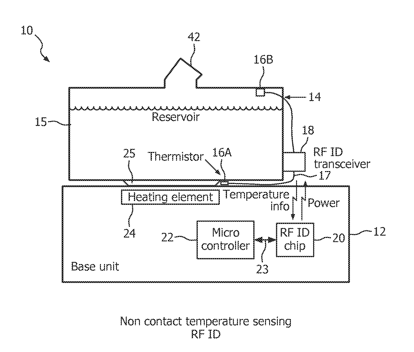
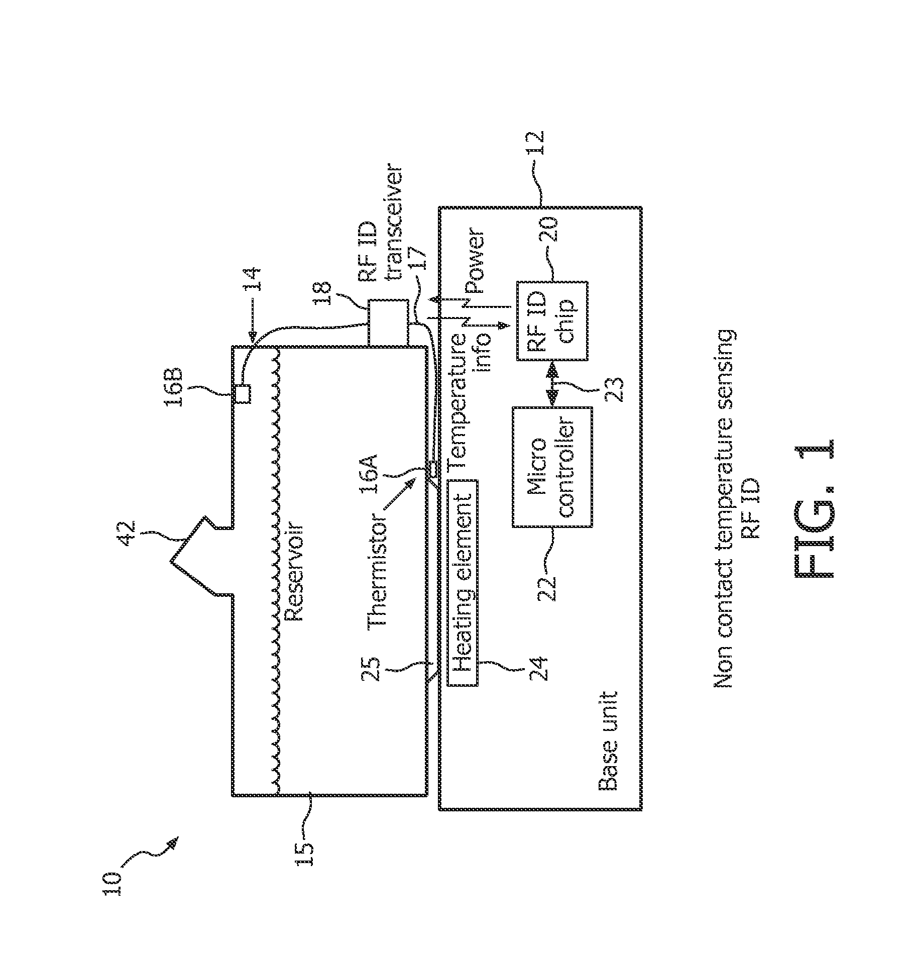
[0016]A humidifier 10 for humidifying a breathing gas for the artificial respiration of a user is described below with reference to FIG. 1. As shown in FIG. 1, humidifier 10 includes a base unit 12 and a chamber 14 constructed and arranged to hold a reservoir of liquid 15. The liquid may be composed primarily, or entirely, of water. Sensors 16A and / or 16B are operatively connected to chamber 14 and are configured to sense a condition within the chamber 14. The condition may be a temperature of the liquid and / or a humidity of gas in chamber 14, or any other condition or parameter, such as, for example, a pressure of the gas within chamber 14, a flow of the gas through the chamber, an oxygen level of the gas in the chamber, and / or a carbon dioxide level of the gas in the chamber. Humidifier 10 may optionally include one or both types of sensors 16A, 16B.

[0017]In some embodiments, sensor 16B may optionally be configured to measure other conditions or parameters, such as, but not limite...


PUM


Abstract

A respiration humidifier having a base unit and a chamber constructed to hold liquid. A sensor is connected to the chamber and configured to sense a condition within the chamber. A radiation signal transmitter is carried by the chamber and associated with the sensor. The transmitter wirelessly sends a radiation signal indicative of the sensed condition. The humidifier includes a radiation signal receiver carried by the base unit for receiving the signal. The humidifier includes a control unit that controls the condition based on the radiation signal received by the radiation signal receiver. Another aspect provides a breathing system using the humidifier. The breathing system includes a gas flow generator that generates a flow of gas to a user circuit coupled to the gas flow generator and adapted to communicate the flow of gas to a user.

Description

CROSS-REFERENCE TO RELATED APPLICATIONS[0001]This patent application claims the priority benefit under 35 U.S.C. §119(e) of U.S. Provisional Application No. 61 / 241,513 filed on Sep. 11, 2009, the contents of which are herein incorporated by reference.BACKGROUND OF THE INVENTION[0002]1. Field of the Invention[0003]The present invention relates to temperature sensing devices of a humidifier reservoir.[0004]2. Description of the Related Art[0005]Various breathing systems use humidifiers to humidify the air being provided to a user. For example, positive airway pressure (PAP) machines provide a continuous positive airway pressure to a user via a suitable user interface (e.g., a mask) for various medical reasons (e.g., to treat sleep apnea). Humidifiers are frequently provided between or integral with the PAP machine and the user interface in order to humidify the otherwise relatively-dry compressed air generated by the PAP machine.[0006]Typically, a temperature sensor is operatively con...

Claims


Application Information

Patent Timeline
Patent Type & Authority Applications(United States)
IPC IPC(8): A61M16/16
CPCA61M16/16A61M2016/0021A61M2016/0039A61M2016/1025A61M2016/103A61M2205/3368A61M16/161A61M2205/3584A61M2205/3592A61M2205/6054A61M11/042A61M16/109A61M2205/3569A61M16/101A61M16/024
Inventor JACOB, LAWRENCE ANTHONY
Owner KONINKLIJKE PHILIPS ELECTRONICS NV
Why Eureka
Try Eureka