
Propellant filling device

Active Publication Date: 2012-07-05
TOYO AEROSOL IND CO LTD
View PDF46 Cites 3 Cited by
  • Summary
  • Abstract
  • Description
  • Claims
  • Application Information

AI Technical Summary

Benefits of technology

[0007]Therefore, when the above conventional filling device is used to fill a propellant into the aerosol container (50) containing a liquid concentrate with relatively high viscosity previously packed therein, the propellant is less likely to be dissolved in the liquid concentrate as compared to a case where a liquid concentrate having relatively low viscosity is packed in the aerosol container (50), and the propellant that is filled into the aerosol container (50) but cannot be dissolved in the liquid concentrate is directly accumulated in a head space (56) of the aerosol container (50) so that the pressure in the aerosol container (50) becomes higher as compared to a case where a low-viscosity liquid concentrate is packed in the aerosol container (50).
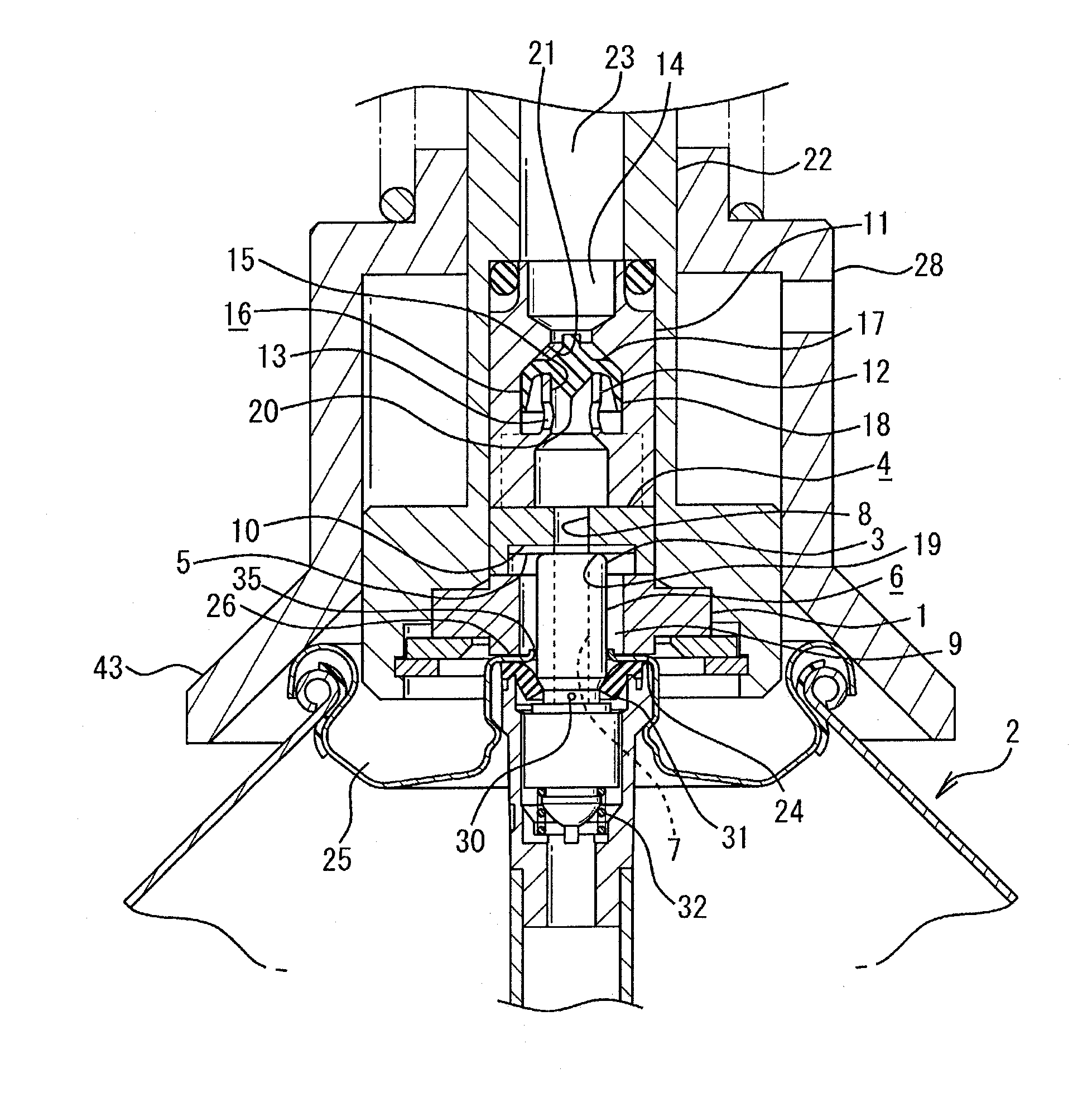
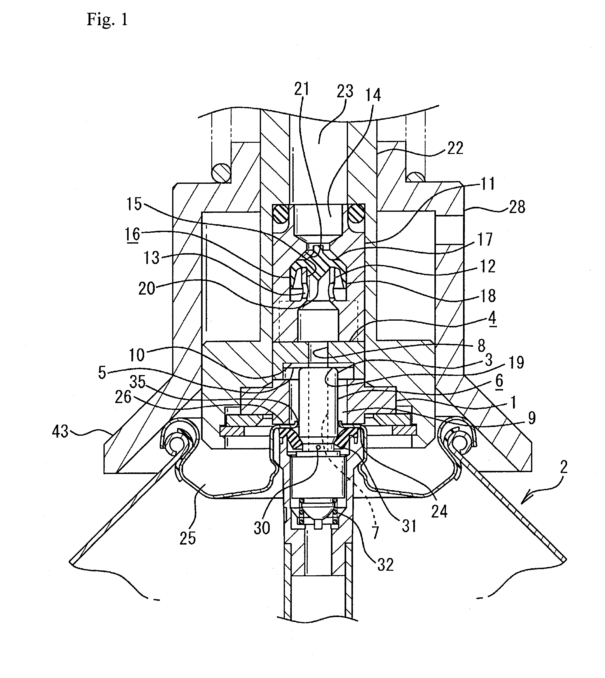
[0028]Further, when the propellant flows under pressure from the supply unit to the aerosol container, the valve member is moved by the pressure of the propellant so that the flow channel can be opened, and when the propellant flows under pressure from the aerosol container to the supply unit side, the flow channel can be closed by the valve member. Therefore, even when the aerosol content contained in the aerosol container flows back, the flow channel is sealed with the valve member by the pressure of the propellant that flows back from the aerosol container, which makes it possible to prevent the backflow of the aerosol content to the supply unit side. Therefore, a situation that the liquid concentrate that flows back from the aerosol container adheres to the inside of the supply channel is less likely to occur, thereby avoiding the disadvantage that, when the aerosol container is detached from the filling device, the liquid concentrate adhering to the inside of the supply channel adheres to the cover etc. of the aerosol container or spatters around the filling device.

Problems solved by technology

However, when a liquid concentrate having relatively high viscosity, such as a foaming agent, is previously packed in the aerosol container (50), it is difficult to agitate the liquid concentrate due to its poor flowability even when the aerosol container (50) is shaken during filling of the propellant into the aerosol container (50).
Therefore, the contact area between the propellant and the liquid concentrate cannot be increased even by such shaking of the aerosol container (50), which makes it difficult to promote the dissolution of the propellant in the liquid concentrate during filling of the propellant into the aerosol container (50).
Therefore, it is difficult to promote the dissolution of the propellant in the liquid concentrate not only by the above-described shaking of the aerosol container (50) but also by the pressure of the propellant supplied from the supply unit.
Therefore, it is difficult to reliably fill a prescribed amount of the propellant into the aerosol container (50).

Method used


Image

  • Propellant filling device
  • Propellant filling device
  • Propellant filling device

Examples


first embodiment

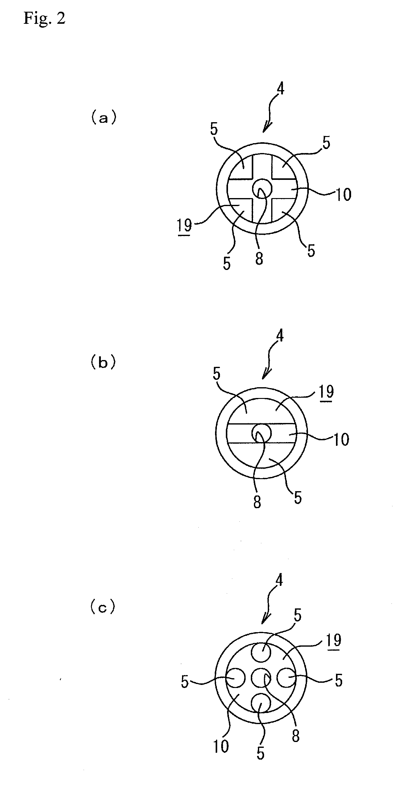
[0037]A first embodiment according to the present invention will be described with reference to FIGS. 1 to 3. As shown in FIG. 1, (1) denotes a sealing member having a cylindrical shape, and a stem projection (3) that projects outward from a stem insertion hole (35) provided in the centre of a cover (25) of an aerosol container (2) is inserted into and placed in the sealing member (1), which makes it possible to cover the outer periphery of the stem projection (3). Further, when the stem projection (3) is inserted into and placed in the sealing member (1), a certain gap (9) is provided between the sealing member (1) and the stem projection (3) placed in the sealing member (1). By providing the sealing member (1) in such a manner as described above, it is possible to seal the space between a valve opening member (4) and a flat surface (26) provided in the centre of the cover (25) of the aerosol container (2).

[0038]The upper end of the sealing member (1) is connected to the lower end ...

second embodiment

[0054]As described above, the valve member (16) according to the first embodiment has a bowl shape formed from the bottom wall (17) and the tapered portion (18) extending from the bottom wall (17) and having a gradually-increasing diameter. However, according to a second embodiment of the present invention, as shown in FIG. 4, the valve member (16) is formed from a flat-shaped plate wall (33). Further, a fitting projection (34) is provided in the centre of the plate wall (33) so as to project from the bottom surface of the plate wall (33). The fitting projection (34) can be fitted into the distal opening (15) of the small flow conduit (12). Therefore, positioning of the valve member (16) can be performed by the fitting projection (34) so that the central portion of the valve member (16) is always located in the distal opening (15).

[0055]When the propellant is supplied from the supply unit through the supply channel (23) to the aerosol container (2) side, the propellant supplied from...

third embodiment

[0059]Each of the above-described propellant filling devices according to the first and second embodiments of the present invention is intended to be used for the aerosol container (2) having a housing and the stem (6) whose lower end portion is inserted into and placed in the housing and whose upper end portion projects outward from the stem insertion hole (35). However, a propellant filling device according to a third embodiment of the present invention and a propellant filling device according to a fourth embodiment of the present invention (which will be described later) are intended to be used for the aerosol container (2) whose stem (6) is not previously fitted thereto, that is, for the aerosol container (2) which has a so-called female-type valve and whose stem (6) is integrally formed with a push button and is connected to the stem insertion hole (35) after the completion of filling of a liquid concentrate and a propellant.

[0060]Herein below, the propellant filling device ac...


PUM

PropertyMeasurementUnit
Pressureaaaaaaaaaa

Abstract

A propellant filling device for filling a propellant into an aerosol container containing a liquid concentrate and the propellant previously filled thereinto includes a valve opening member that continuously presses a valve member to open a valve system of the aerosol container and has a communicating hole. On the upper end side of the valve opening member, a flow conduit is provided. A valve member is provided in the flow conduit to allow a flow channel of the flow conduit to be closed. The valve system is kept in an open state, and when the pressure in the aerosol container is higher than the supply unit side pressure, the backflow of aerosol content is prevented, and when the supply unit side pressure is higher than the pressure in the aerosol container, the propellant flows into the aerosol container.

Description

BACKGROUND OF THE INVENTION[0001]The present invention relates to a propellant filling device for use in filling a propellant into an aerosol container through a valve system of the aerosol container.[0002]As devices for use in pressure-filling a propellant into an aerosol container, propellant filling devices such as one disclosed in Patent Document 1 are conventionally used. It is to be noted that Patent Document 1 discloses a propellant filling device adapted to be connected to the stem side of an aerosol container to fill a propellant into a bag in the aerosol container through an ejection hole of the stem.[0003]Among such filling devices, a filling device as shown in FIG. 8 is conventionally used as a filling device for use in through-the-valve filling, which is a general method for filling a propellant. The filling device shown in FIG. 8 is intended to be used with a general aerosol container (50) having a valve system (55) and a stem (51) whose lower end is pre-fitted to the ...

Claims


Application Information

Patent Timeline
IPC IPC(8): B65B31/04
CPCB65B31/003B65B31/00B65B31/10
Inventor HOSODA, TAKAFUMIIUCHI, YOSHIKAZUHANAI, NOBUYUKISHIBATA, TAKUO
Owner TOYO AEROSOL IND CO LTD
Learn More