Voltage regulator

a voltage regulator and voltage field technology, applied in the direction of electric variable regulation, process and machine control, instruments, etc., can solve the problems of voltage regulator application problems, overcurrent value failure to be confirmed, and voltage regulator application problems

Active Publication Date: 2012-07-05
FARADAY TECH CORP
View PDF2 Cites 21 Cited by
  • Summary
  • Abstract
  • Description
  • Claims
  • Application Information

AI Technical Summary

Benefits of technology

[0031]It is an object of the invention to provide a voltage regulator with a fold-back overcurrent protection circuit, in which the overcurrent

Problems solved by technology

It causes the application of the voltage regulator problem.
However, the process deviation causes an error of the resistor R103, and thus the overcurrent value fails to be confirmed.
It causes problems in the applica

Method used


Image

  • Voltage regulator
  • Voltage regulator
  • Voltage regulator

Examples


first embodiment

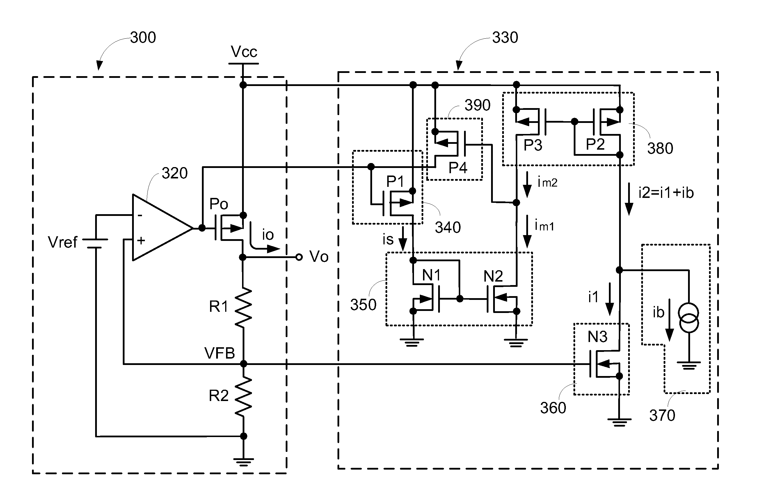
[0058]According to the invention, when the voltage regulator is in normal operation, the constant current providing unit 370 supplies a constant current ib, and the divided voltage VFB controls the current converting unit 360 to generate the first current i1. Therefore, the second current i2 is the sum of the first current i1 and the constant current ib. And, the second mirroring unit 380 generates the second mirror current im2. The second mirror current im2 is the threshold current signal for determining whether the overcurrent protection circuit 330 starts up or not.

[0059]Furthermore, the current sensing unit 340 and the first mirroring unit 350 show the first mirroring current im1 is proportional to the output current io. According to a proper design, when the output current io is smaller than the overcurrent value, the first mirroring current im1 is less than the second mirror current im2, so that the pull up unit 390 is disabled. On the other hand, when the output current io re...

second embodiment

[0062]Please refer to FIG. 6A, a voltage regulator with a fold-back overcurrent protection circuit according to the invention. Wherein, the voltage regulator with the fold-back overcurrent protection circuit of the invention includes a constant voltage power circuit 300 and an overcurrent protection circuit 335.

[0063]The difference of the second embodiment and the first embodiment is a constant current providing unit 375. The constant current providing unit 375 of the second embodiment sets a start-up current limit when the voltage regulator starts up. And, when the short circuit occurs at the constant voltage power circuit 300, the output current io decreases to zero. In other words, the minimum current limit of the voltage regulator is zero.

[0064]The constant current providing unit 375 includes a constant current source, a latch 378, a switch transistor N4, and a third resistor R3. The latch 378 has a set terminal S, a reset terminal R and an output terminal C. The constant curren...


PUM


Abstract

A voltage regulator includes a constant voltage power circuit and an overcurrent protection circuit. The constant voltage power circuit generates an output voltage, an output current and a divided voltage. The overcurrent protection circuit includes a current sensing unit, a first mirroring unit, a voltage to current converting unit, a second mirroring unit, and a pull up unit. The current sensing unit generates a sensing current according to the output current. The first mirroring unit generates a first mirroring current. The first mirroring current is proportional to the output current. The voltage to current converting unit is used for converting the divided voltage into a first current.
The second mirroring unit generates a second mirroring current. The second mirroring current is proportional to the second current. The pull up unit controls the output voltage and the output current according to the first mirroring current and the second mirroring current.

Description

[0001]This application claims the benefit of Taiwan Application No. 100100237, filed Jan. 4, 2011, the subject matter of which is incorporated herein by reference.FIELD OF THE INVENTION[0002]The present invention relates to a voltage regulator, and more particularly to a voltage regulator with a fold-back overcurrent protection circuit.BACKGROUND OF THE INVENTION[0003]A voltage regulator having an overcurrent protection circuit limits an output current to prevent the voltage regulator from being burned when the output current exceeds an overcurrent value. In addition to the function of limiting the output current to be below the overcurrent value, the voltage regulator with a fold-back overcurrent protection circuit reduces the output current when an output voltage is lowered. Therefore, it prevents the voltage regulator from being burned and reduces power consumption.[0004]Please refer to FIG. 1A and FIG. 1B. FIG. 1A is a circuit diagram of a voltage regulator with a drooping type ...

Claims


Application Information

Patent Timeline
IPC IPC(8): G05F1/10
CPCG05F1/573
Inventor CHEN, CHI-YANG
Owner FARADAY TECH CORP
Why Eureka
Try Eureka