Water leak detection and shut-off method and apparatus using differential flow rate sensors

a technology of differential flow rate and water leak detection, applied in the direction of fluid tightness measurement, valve operating means/release devices, instruments, etc., can solve the problems of increasing the probability of leakage, electrolytic water leak detection is effective, and many different locations are affected

Inactive Publication Date: 2014-06-10
CONTROL AIR CONDITIONING
View PDF9 Cites 44 Cited by
  • Summary
  • Abstract
  • Description
  • Claims
  • Application Information

AI Technical Summary

Benefits of technology

[0030]The solenoid shut-off valve is a normally closed valve which opens to allow flow only when supplied with continuous electrical power. Therefore, if a leak rate which exceeds a predetermined limit value occurs, or if electrical power is interrupted to the building mains which supply power to the control apparatus, according to the present invention, the upstream shut-off valve immediately and automatically closes and interrupts the flow of hot water from the hot water source riser line to a destination which is downstream from the apparatus, such as a VAV terminal. Thus, in the event of a detected water leak or interruption of building power, the apparatus according to the present invention is effective in immediately terminating flow of hot water beyond the upstream shut-off valve. Optionally and desirably, the alarm status signal would also be sent to building maintenance stations to inform maintenance personnel of a detected leak.
[0031]A preferred embodiment of a leak detection method and apparatus according to the present invention also includes a normally closed, solenoid actuated downstream shut-off valve, which may be identical to the upstream shut-off valve. The downstream shut-off valve is located between the downstream flow rate sensor and the Hot Water Return (HWR) riser pipe. The downstream shut-off valve is operated in unison with the upstream shut-off valve, i.e., it is closed when a leak of a predetermined minimum value occurs, or if electrical power to the building is interrupted. The downstream shut-off valve is provided in addition to the upstream shut-off valve to prevent any water to the riser HWS or HWR lines from flowing back to the area where the leak has been detected.

Problems solved by technology

Thus there is the possibility of a leak developing at many different locations in the closed-loop system, the probability of which is increased in the event of seismic disturbance of the building.
However, such electrolytic water leak sensors are effective only in detecting water leakage at discrete locations where the sensors are placed.
This is because a water leak detection system using point sensors for systems such as closed-loop water circulating systems which extend over a large area would require an unreasonably large number of individual sensors which were placed near every possible leakage point.
That the detection and abatement of water leaks in contemporary buildings is an important problem is evidenced by two recent cases in California, where leakage from broken building hot water circulation systems caused more than one million dollars worth of damage in each of the buildings.
Part of the expenses associated with water leaks in buildings results from modern building codes and potential legal liability which require the complete removal and replacement of all drywall that has been subjected to water leaks for more than 72 hours, to prevent the growth of molds which can cause health problems.
More important than potential financial losses which can result from water leakage that is not timely detected and abated is the possibility of serious injury or even death which can result if a leak in a hot water circulation system of a hospital building should occur.
For example, a hot water leak may allow sufficient water to accumulate, leak through ceilings and scald patients in their beds on lower floors.

Method used


Image

  • Water leak detection and shut-off method and apparatus using differential flow rate sensors
  • Water leak detection and shut-off method and apparatus using differential flow rate sensors
  • Water leak detection and shut-off method and apparatus using differential flow rate sensors

Examples


Embodiment Construction

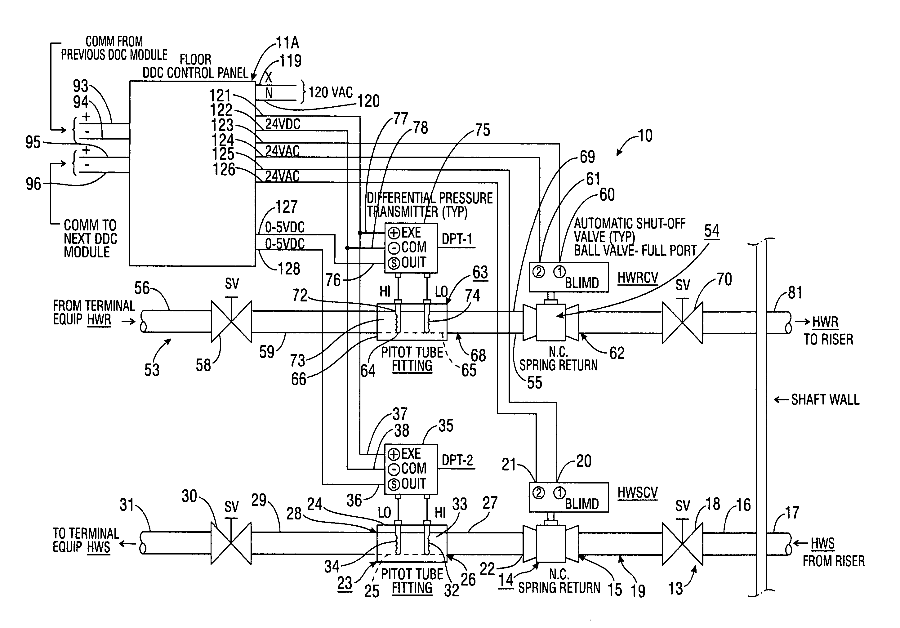
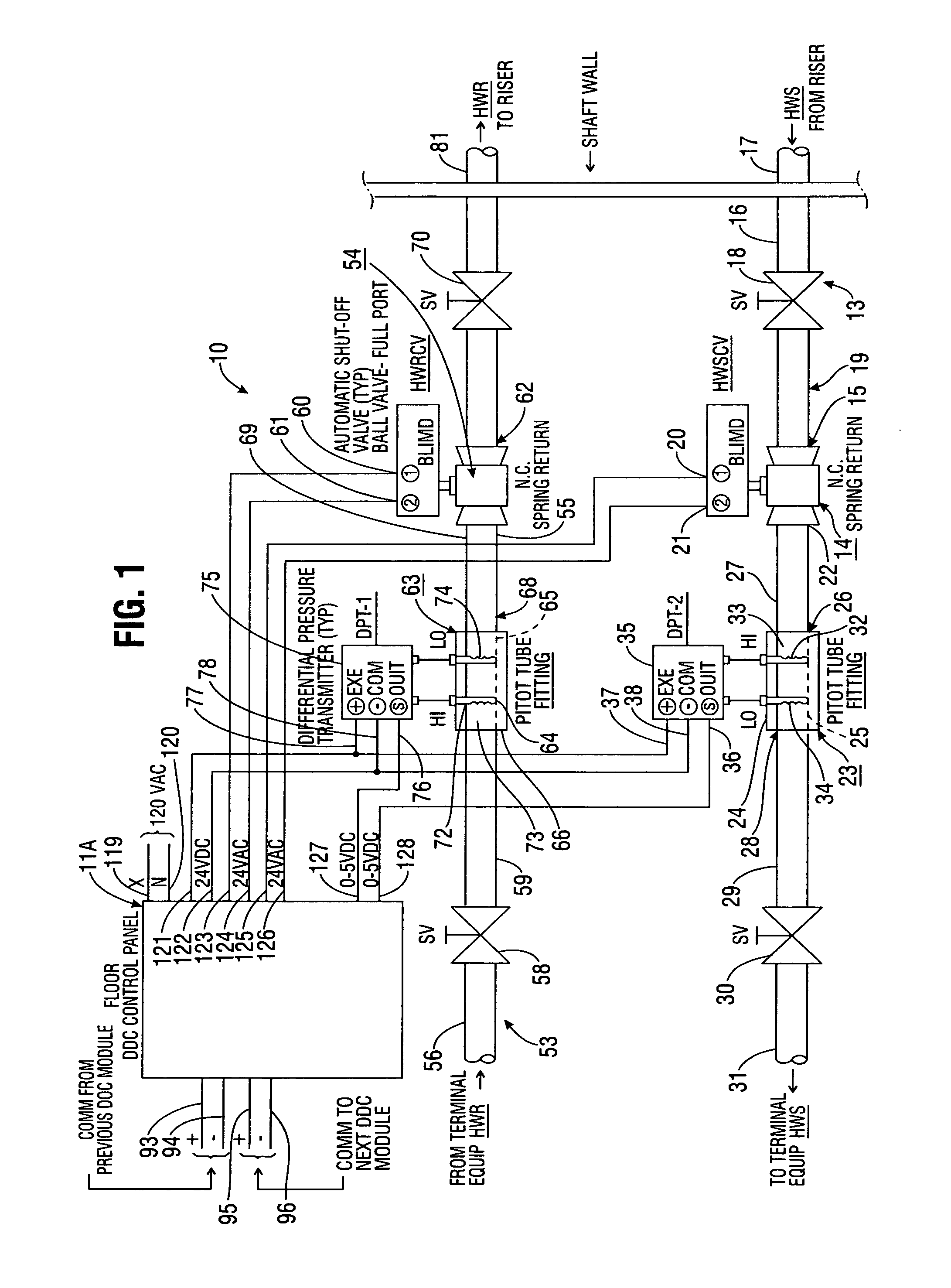
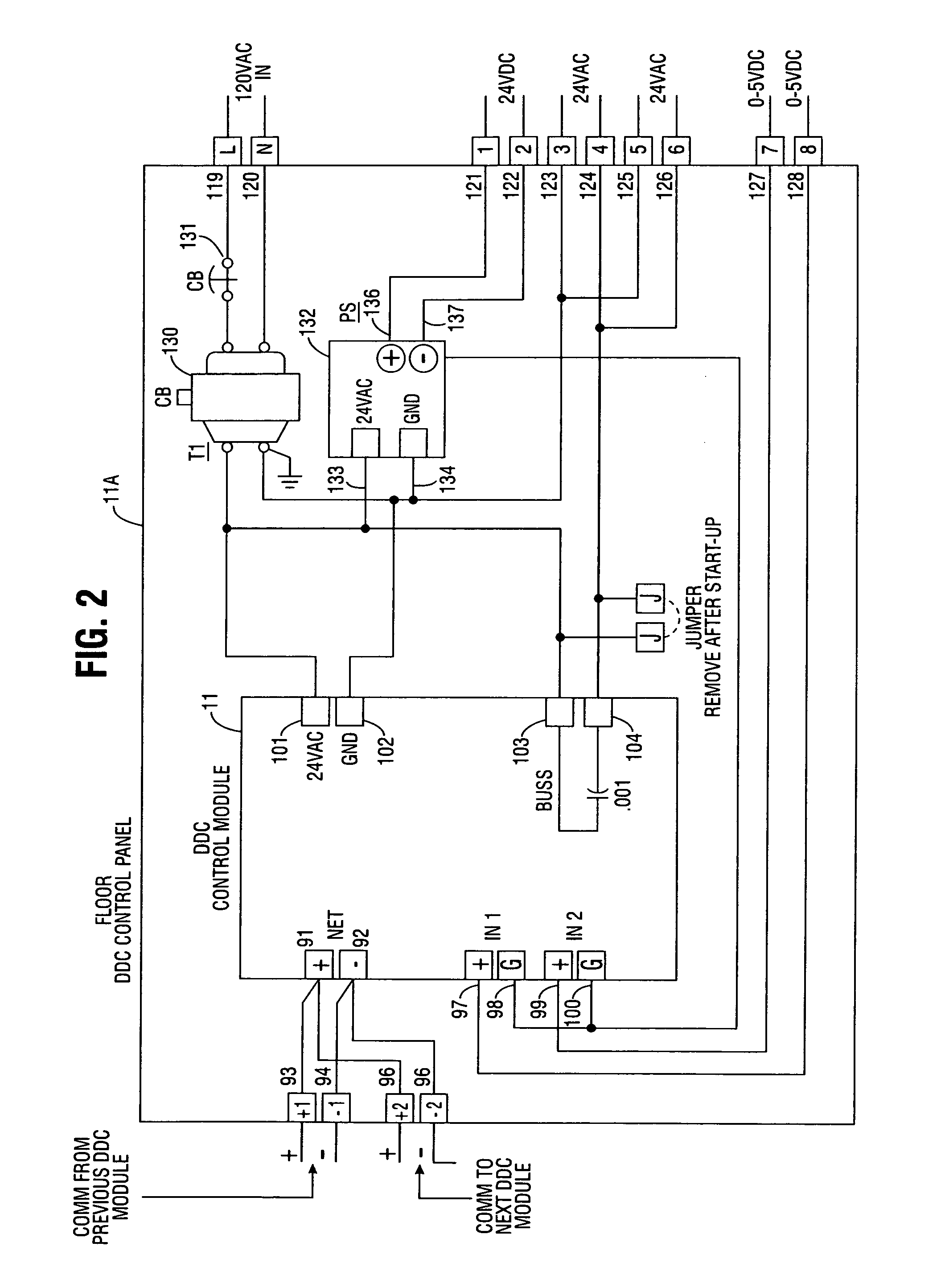
[0035]FIG. 1 illustrates a basic embodiment of water leak detection and shut-off apparatus 10 using differential flow rate sensors according to the present invention. FIG. 2 is a more detailed schematic view of a control panel 11A and control module 11 comprising part of the apparatus 10 of FIG. 1. FIG. 3 is a partly diagrammatic view of a Variable Air Volume (VAV) terminal 12 which; typifies a terminal component of a closed-loop water circulation system of a type which apparatus 10 is intended for use with.

[0036]Referring now to FIG. 1, it may be seen that water leak detection and shut-off apparatus 10 according to the present invention includes an upstream inlet port 13 for receiving a flowing liquid such as hot water which is pressurized above ambient atmosphere pressure by a pump and / or a gravity pressure head, i.e., from a pump at any elevation or a tank at a higher elevation than inlet port 13. Upstream inlet port 13 is connected by a fluid pressure-tight tube or pipe to the i...


PUM


Abstract

A method and apparatus for detecting leakage of flowing liquids from pipes includes an upstream flow-rate sensor positioned between a source of a flowing liquid which is conducted from a source to a destination terminal such as a VAV heat exchanger, and a downstream flow-rate sensor positioned between an outlet port of the destination terminal and a return line for the flowing liquid. The apparatus includes electronic control circuitry which is responsive to a differential flow-rate between upstream and downstream measured flow rates which exceeds a predetermined limit value in removing a valve-opening signal to the upstream shut-off valve, thus closing the valve to interrupt flow of liquid through the valve if the differential flow-rate signifies a leak. Optionally, the apparatus also includes a downstream shut-off valve positioned between the destination terminal and a return line, which is also closed in response to a differential flow-rate exceeding the limit value.

Description

BACKGROUND OF THE INVENTION[0001]A. Field of the Invention[0002]The present invention relates to methods and apparatus for detecting and abating leaks of flowing liquids from pipes in buildings and similar structures. More particularly, the invention relates to a method and apparatus which uses differential flow rate sensors for detecting water leaks, particularly in closed loop water circulation systems, and solenoid valves to shut off water flow if a detected leak rate exceeds a predetermined value.[0003]B. Description of Background Art[0004]Contemporary buildings of various types, and particularly hospitals, institutional buildings, and larger commercial and industrial buildings employ a variety of water distribution piping or plumbing systems. Thus, in addition to plumbing used to supply potable water for consumption by the building' occupants, highly purified water for use in production processing, or lower quality water for other purposes, many larger contemporary buildings al...

Claims


Application Information

Patent Timeline
Patent Type & Authority Patents(United States)
IPC IPC(8): F16K17/00G08B21/00G01M3/24F16K31/00A62C37/50G01M3/00F17D5/02G01M3/28G01M3/04G01M3/32
CPCG01M3/3254G01M3/2807F17D5/02A62C37/50G01M3/243G01M3/2876G01M3/2815A62C35/68A62C35/60Y10T137/7759Y10T137/7734Y10T137/776Y10T137/7727
Inventor TOLLEFSON, ROBIN
Owner CONTROL AIR CONDITIONING
Why Eureka
Try Eureka