Color filter substrate and liquid crystal display device

a liquid crystal display and substrate technology, applied in the direction of optics, instruments, optical elements, etc., can solve the problems of short circuit (leakage) between electrodes, display failure, and damage to the insulation film, so as to prevent short circuit between the substrate and other members and secure the stability of display quality in the display portion

Inactive Publication Date: 2012-07-05
SHARP KK
View PDF5 Cites 17 Cited by
  • Summary
  • Abstract
  • Description
  • Claims
  • Application Information

AI Technical Summary

Benefits of technology

[0046]According to the color filter substrate of the present invention, a short circuit between the substrate and other members can be prevented and an area originally used as a color filter can be sufficiently worked. Further, according to the LCD device of the present invention, a short circuit between a pair of substrates that face each other through a multi-layer spacer is prevented and stable display quality can be secured in a display portion.

Problems solved by technology

Even if an insulating film is formed on a multi-layer spacer, the insulating film may be damaged by pressure from the multi-layer spacer to which external pressure is applied, when the durability of the insulating film is insufficient.
Further, a fitting gap may be created to cause a short circuit (leak) between electrodes disposed on each of a pair of substrates.
Thereby, display failure maybe caused.
A display device including such a color filter substrate cannot provide stable display.

Method used


Image

  • Color filter substrate and liquid crystal display device
  • Color filter substrate and liquid crystal display device
  • Color filter substrate and liquid crystal display device

Examples


embodiment 1

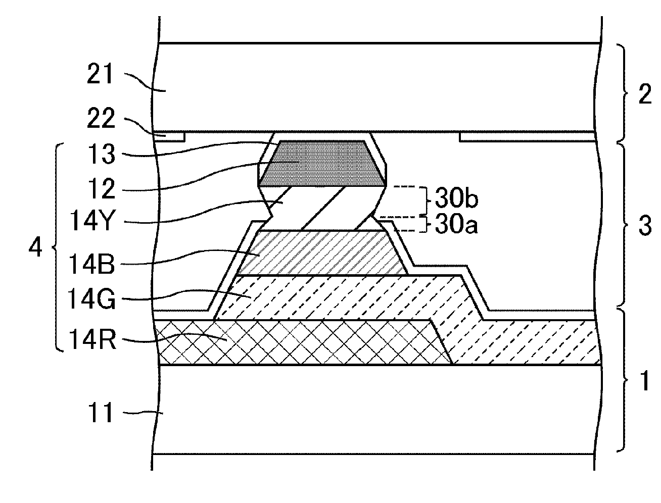
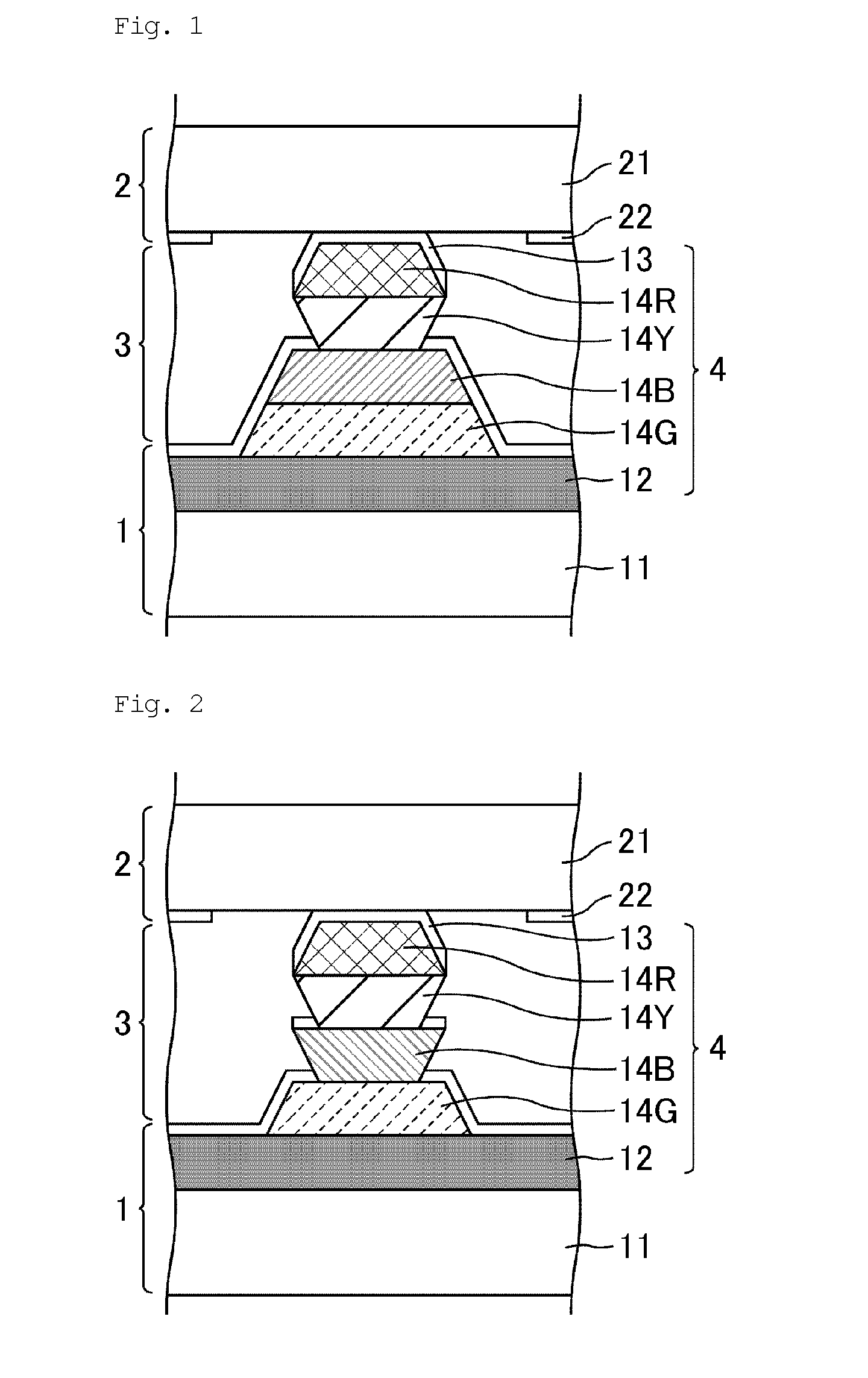
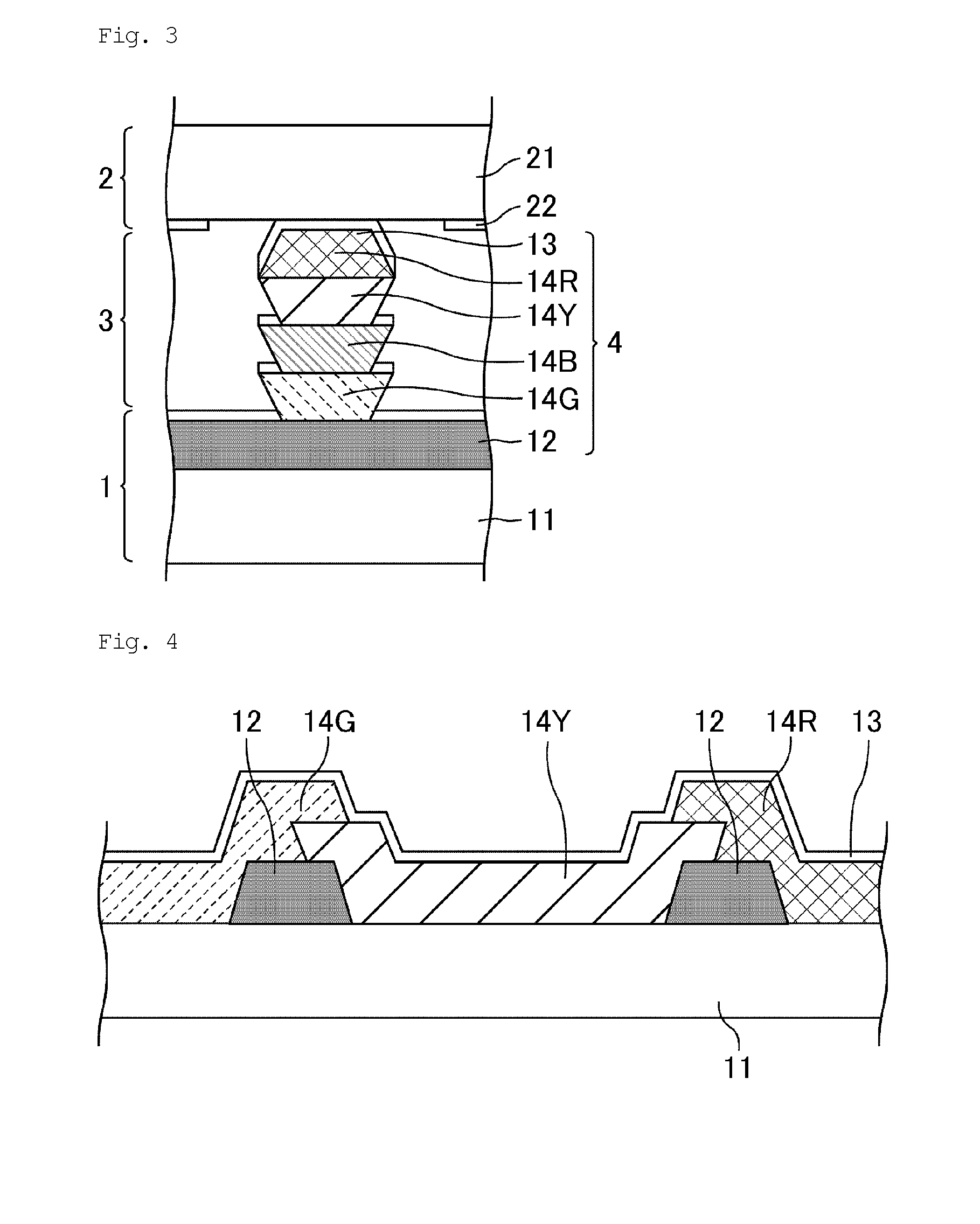
[0063]Embodiment 1 is one embodiment of a liquid crystal display device including a first color filter substrate of the present invention. FIG. 1 is a schematic cross-sectional view of a spacer portion of a liquid crystal display (hereinafter, referred to as LCD) device of Embodiment 1. As shown in FIG. 1, the LCD device of Embodiment 1 has a configuration where a liquid crystal layer 3 is disposed between a color filter substrate 1 and an array substrate 2, and a multi-layer spacer 4 is disposed between the color filter substrate 1 and the array substrate 2, as a member for fixing a distance (cell gap) therebetween. The multi-layer spacer 4 is formed in the color filter substrate 1.

[0064]The color filter substrate 1 and the array substrate 2 mainly include insulating substrates 11 and 21, respectively. The substrates 11 and 21 are made from glass, resins, or the like.

[0065]The multi-layer spacer 4 includes a black matrix (light shielding layer) 12, a green color filter (colored tra...

embodiment 2

[0091]Embodiment 2 is one embodiment of a liquid crystal display device including a second color filter substrate of the present invention. The LCD device of Embodiment 2 has the same configuration as that of Embodiment 1 except for the configuration of the color filter substrate in a spacer portion and the configuration of the color filter substrate in a display portion.

[0092]FIG. 6 is a schematic cross-sectional view of a spacer portion of an LCD device of Embodiment 2. As shown in FIG. 6, the LCD device of Embodiment 2 has a configuration where a liquid crystal layer 3 is disposed between a color filter substrate 1 and an array substrate 2, and a multi-layer spacer 4 is disposed between the color filter substrate 1 and the array substrate 2 as a member for fixing a distance (cell gap) therebetween. The multi-layer spacer 4 is formed in the color filter substrate 1. The top of the multi-layer spacer 4 is in contact with the array substrate 1.

[0093]The multi-layer spacer 4 in Embod...

embodiment 3

[0101]Embodiment 3 is one embodiment of a liquid crystal display device including a first color filter substrate of the present invention or a second color filter substrate of the present invention. The LCD device of Embodiment 3 has the same configuration as that of Embodiments 1 or 2 except for the configuration of the color filter substrate in a spacer portion and the configuration of the color filter in a display portion.

[0102]FIG. 11 is a schematic cross-sectional view of a spacer portion of an LCD device of Embodiment 3. As shown in FIG. 11, the LCD device of Embodiment 3 has a configuration where a liquid crystal layer 3 is disposed between a color filter substrate 1 and an array substrate 2, and a multi-layer spacer 4 is disposed between the color filter substrate 1 and the array substrate 2 as a member for fixing a distance (cell gap) therebetween. The multi-layer spacer 4 is formed in a color-filter-substrate 1.

[0103]The multi-layer spacer 4 in Embodiment 3 includes a blac...


PUM

PropertyMeasurementUnit
transparentaaaaaaaaaa
colorsaaaaaaaaaa
distanceaaaaaaaaaa

Abstract

The present invention provides a color filter substrate for preventing an electrical short circuit between an electrode and other members at a place upper than the colored transparent layers disposed in a stack, and further preventing electrical disconnection on colored transparent layers other than the colored transparent layers in a stack, in the case where colored transparent layers are disposed in a stack and an electrode is stacked over the entire surface. The color filter substrate of the present invention comprises:
    • colored transparent layers disposed side by side; and
    • colored transparent layers disposed in a stack,
    • wherein an electrode is disposed at a place upper than the colored transparent layers disposed side by side and an electrode is disposed at a place upper than the colored transparent layers disposed in a stack,
    • the colored transparent layers disposed in a stack include a colored transparent layer having a reverse tapered shape, and
    • the uppermost layer of the colored transparent layers disposed in a stack has a forward tapered shape.

Description

TECHNICAL FIELD[0001]The present invention relates to a color filter substrate and a liquid crystal display device. More specifically, the present invention relates to a color filter substrate including color filters disposed in a stack and a liquid crystal display device including such a color filter substrate.BACKGROUND ART[0002]A liquid crystal display (LCD) device includes a pair of substrates and a liquid crystal layer disposed between the substrates, and performs display in such away that an alignment state of liquid crystal molecules is changed by applying a voltage to the liquid crystal layer using electrodes formed in the substrates and a polarization state of light passing through the liquid crystal layer is changed. An LCD device performing color display has a color filter substrate including a plurality of color filters different in colors.[0003]A pair of substrates of an LCD device is attached to each other with a sealing material. A distance (cell gap) between the pair...

Claims


Application Information

Patent Timeline
Patent Type & Authority Applications(United States)
IPC IPC(8): G02F1/1335
CPCG02B5/201G02F1/133512G02F1/13394G02F1/1339G02F1/133514
Inventor TSUBATA, TOSHIHIDE
Owner SHARP KK
Why Eureka
Try Eureka