
Optical device with a piezoelectrically actuated deformable membrane shaped as a continuous crown

a deformation membrane and optical device technology, applied in piezoelectric/electrostrictive/magnetostrictive devices, instruments, camera body details, etc., can solve the problems of low optical performance of the device, low energy consumption upon actuation, and inability to provide the expected feedback. , to achieve the effect of reducing optical aberration

Active Publication Date: 2012-07-05
WEBSTER CAPITAL LLC
View PDF7 Cites 36 Cited by
  • Summary
  • Abstract
  • Description
  • Claims
  • Application Information

AI Technical Summary

Benefits of technology

[0013]Another object of the invention is to provide an optical device with a deformable membrane wherein the optical aberrations are reduced.
[0027]The piezoelectric actuators are separately actuatable from each other or they are simultaneously actuatable all together or even they are simultaneously actuatable by groups. This provides great flexibility to achieve a wanted deformation of the membrane in the central area.

Problems solved by technology

One drawback in this configuration is that it is bulky since the actuating means lean on the support.
Another drawback is that for a given bulk, and a given energy consumption, upon actuation, optical performances of the device are not optimum.
Similarly, for a given bulk, and given optical performances, the energy consumption is high upon actuation.
The rigidity of this cover acts as a brake on the actuating efficiency and the material contained in the cavity, because it is of the gel or elastomer type, does not provide the expected feedback under the effect of actuation to deform the central area of the covers.
Such an optical device has a poor performance.

Method used


Image

  • Optical device with a piezoelectrically actuated deformable membrane shaped as a continuous crown
  • Optical device with a piezoelectrically actuated deformable membrane shaped as a continuous crown
  • Optical device with a piezoelectrically actuated deformable membrane shaped as a continuous crown

Examples


Embodiment Construction

[0011]One object of the present invention is precisely to provide an optical device with a deformable membrane such as a lens or mirror which does not have the abovementioned drawbacks, that is bulk, high energy consumption and poor actuating efficiency.

[0012]Another object of the invention is to provide an optical device with a deformable membrane, of which the deformation of the membrane can be intentionally and very finely adjusted, whether the deformation is symmetrical or not, with respect to an optical axis of the optical device.

[0013]Another object of the invention is to provide an optical device with a deformable membrane wherein the optical aberrations are reduced.

[0014]Another object of the invention is to provide an optical device with a deformable membrane wherein the residual stresses occurring upon manufacturing are easier to manage during use.

[0015]Still another object of the invention is to provide an optical device with a deformable membrane, having an active compen...


PUM


Abstract

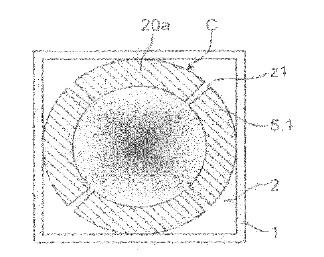
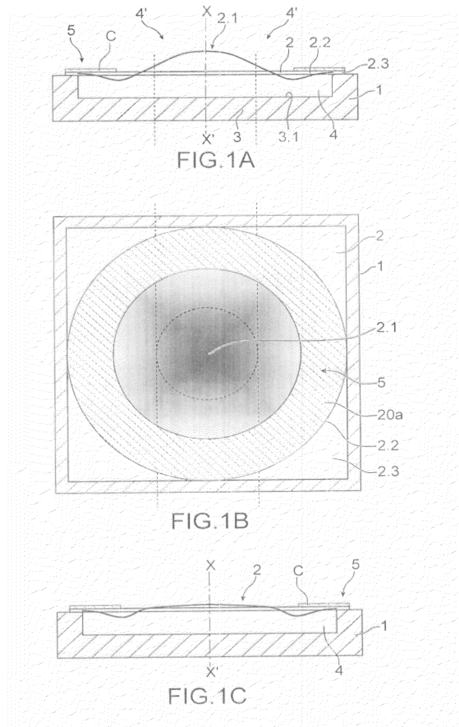
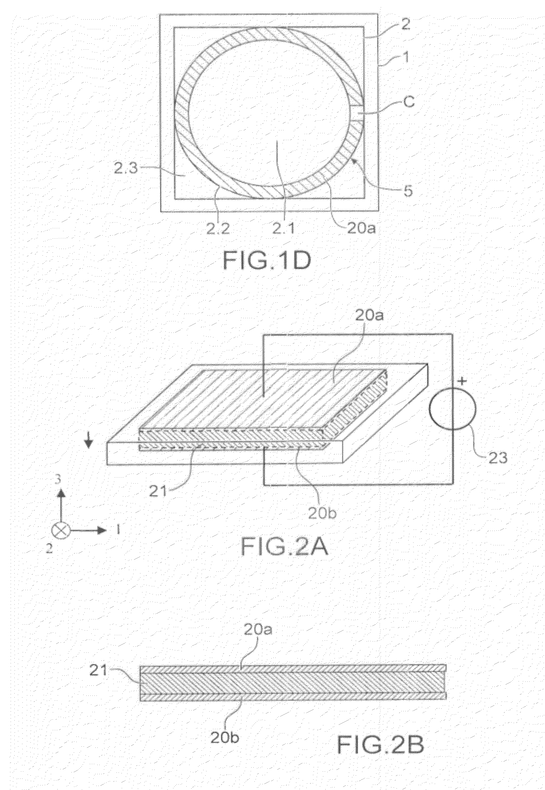
An optical device with a deformable membrane (2) including an anchor area (2.3) on a support (1) entrapping a liquid or gas fluid, a central area (2.1) reversibly deformable from a rest position, actuating means for moving the fluid (4) biasing the membrane (2) into an intermediate area between the anchor area (2.3) and the central area (2.1), the actuating means include a piezoelectric continuous crown accommodating several actuators (5.1), this crown surrounding the central area (2.1), the actuating means (5) being anchored to the membrane (2) in at least the intermediate area (2.2), the actuating means (5) and the membrane (2) to which they are anchored, forming at least one piezoelectric bimorph (B), the actuating means (5) radially contracting or extending upon actuation so as to generate a movement of said fluid (4) from the intermediate area (2.2) to the central area (2.1) of the membrane (2) or vice versa, aiming at deforming the central area (2.1) with respect to its rest position.

Description

TECHNICAL FIELD[0001]The present invention relates to an optical device with a deformable membrane entrapping a fluid and provided with means for actuating the piezoelectric type membrane to adjust the radius of curvature of the membrane in its central part. Such an optical device with a deformable membrane can be a variable focus liquid lens, an optical aberration correcting liquid lens for active optics, or a variable focus mirror.[0002]Liquid lenses are usable for example in portable phones with a camera function. Numerous developments are underway, among which in particular the autofocus function and the zoom function. It is attempted, upon introduction of these functions, to obtain as short a response time as possible but also to decrease the energy consumption upon actuation and to increase variations in the focus at a given energy consumption, while avoiding a complex manufacture of such apparatuses. More globally, it is attempted to integrate as many components as possible o...

Claims


Application Information

Patent Timeline
IPC IPC(8): G03B17/00G02B3/14
CPCG02B3/14G02B3/12H01L41/098G02B26/0825H10N30/2048G02B26/004G02B27/0068
Inventor MOREAU, STEPHANEBOLIS, SEBASTIEN
Owner WEBSTER CAPITAL LLC
Learn More