Method of aligning handles in rows for a rotating blow-molding machine for handled-bottles

a blow-molding machine and handle technology, applied in domestic applications, thin material processing, article separation, etc., can solve the problems of difficult implementation, speed of handle alignment cannot match the high production speed of the rotating blow-molding machine, and the blow-molding machine for handled bottles is not widely used commercially

Inactive Publication Date: 2012-07-05
BOTTLE TOP DEV
View PDF3 Cites 0 Cited by
  • Summary
  • Abstract
  • Description
  • Claims
  • Application Information

AI Technical Summary

Benefits of technology

[0004]Therefore the primary object of the present invention is to solve the aforesaid conventional problem by providing a plurality of row aligning modules in a rotating blow-molding machine for handled-bottles. The row aligning modules are provided at a number same as bottle blowing modules to form a plurality of common modules. Each row aligning module provides an aligned handle to a corresponding bottle blowing module. Thus the bottleneck of high speed synchronized production process required in the rotating blow-molding machine can be overcome.
[0006]Thus, by pairing the row aligning modules and the bottle blowing modules to form the common modules the row aligning modules can be rotated with the bottle blowing modules without synchronization problem of handle movement at high speed between them. Moreover, each row aligning module arranges its own handles. In one process cycle of the rotating blow-molding machine each row aligning module needs to provide only one aligned handle. Hence there is sufficient time to arrange the handles in rows to prevent the high speed production bottleneck that requires high speed row alignment for the rotating blow-molding machine for handled-bottles.

Problems solved by technology

The rotating handled-bottles blow-molding machine still is not widely used commercially.
The main bottleneck is that the speed of handle alignment cannot match the high production speed of the rotating blow-molding machine.
However, it would be more difficult to implement, need a great deal of equipments, and has higher cost.

Method used


Image

  • Method of aligning handles in rows for a rotating blow-molding machine for handled-bottles
  • Method of aligning handles in rows for a rotating blow-molding machine for handled-bottles
  • Method of aligning handles in rows for a rotating blow-molding machine for handled-bottles

Examples


Embodiment Construction

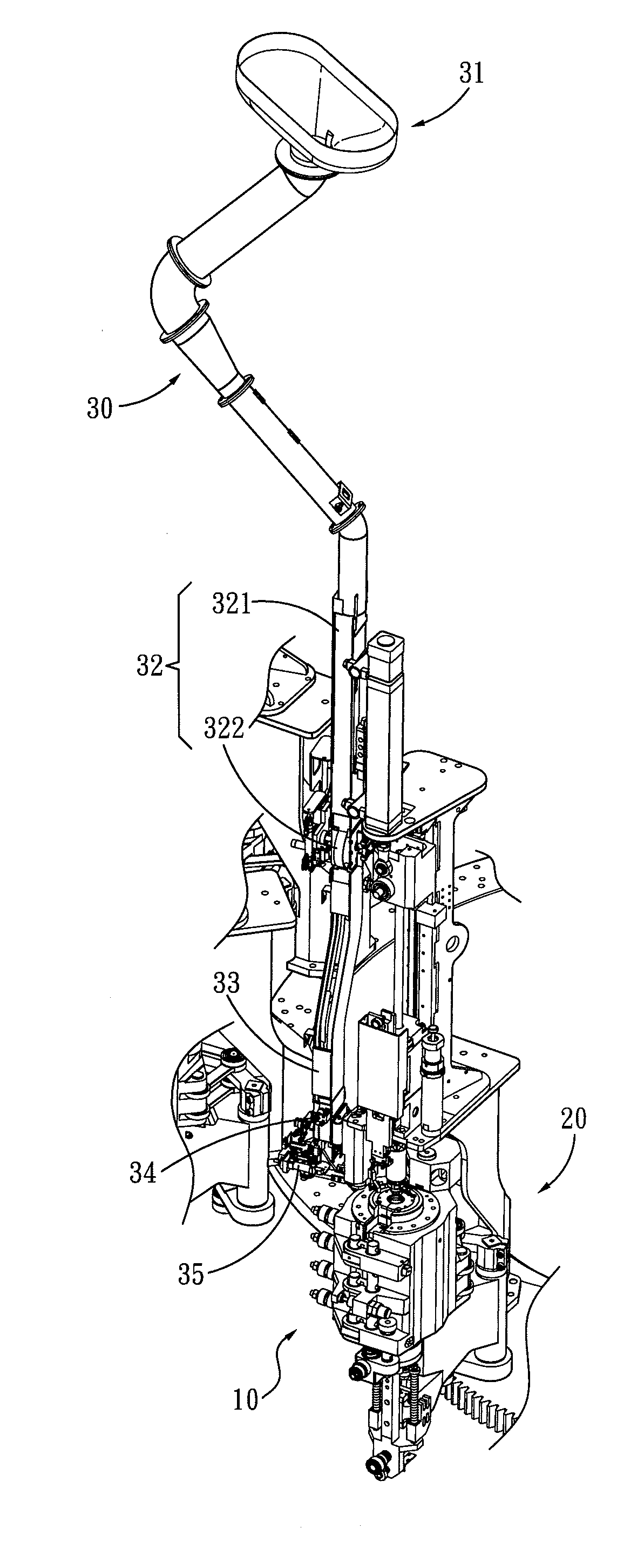
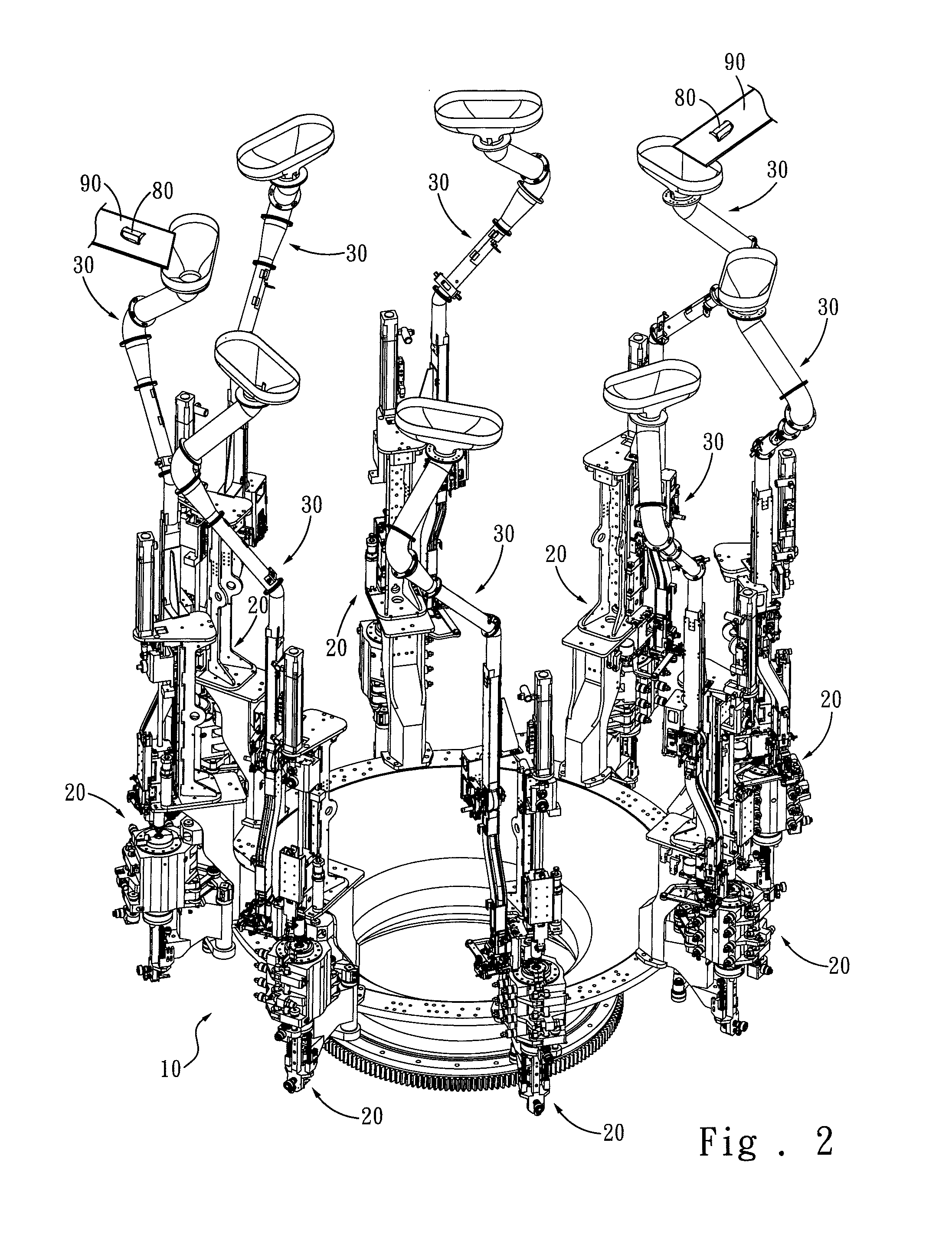
[0018]Please referring to FIGS. 2 and 3, the present invention discloses a method of aligning handles in rows to provide a plurality of aligned handles 80 to a rotating blow-molding machine 10. The rotating handled-bottle blow-molding machine 10 has a plurality of bottle blowing modules 20; eight is taken as an example for discussion below, but shall not be deemed as the limitation of the present invention. The method of the present invention includes the steps of: providing at least one handle conveying device 90 at a number not greater than that of the bottle blowing modules 20 to provide unaligned handles 80; and providing a plurality of row aligning modules 30 at a number same as the bottle blowing modules 20 to be paired therewith to form a plurality of common modules. The row aligning modules 30 receive the handles 80 from the handle conveying device 90 and align the handles 80 in rows and send them to the corresponding bottle blowing modules 20.

[0019]Each of the row aligning ...


PUM

PropertyMeasurementUnit
speedaaaaaaaaaa
gravityaaaaaaaaaa
timeaaaaaaaaaa

Abstract

A method of aligning handles in rows for a rotating blow-molding machine for handled-bottles includes steps of: providing at least one handle conveying device to provide a plurality of unaligned handles, and providing a plurality of pairs of row aligning modules and bottle blowing modules to form a plurality of common modules. The row aligning modules receive the handles from the handle conveying device and arrange the handles in rows and send the aligned handles to the corresponding bottle blowing modules. Thus the row aligning modules are rotated synchronously with the corresponding bottle blowing modules without the problem of handle transport synchronization during high speed, and sufficient time is provided to align all the handles in rows.

Description

FIELD OF THE INVENTION[0001]The present invention relates to a method of aligning handles of bottles in row and particularly to a method of aligning handles in rows for a rotating blow-molding machine for handled-bottles.BACKGROUND OF THE INVENTION[0002]Rotating blow-molding machine for handled-bottles provides many advantages, such as mass production, save space and the like, thus is widely employed to produce various types of liquid containers used in households. For a bottle 1 with a large capacity a handle 2 usually is provided as shown in FIG. 1 to facilitate grasping and using.[0003]In a conventional handled-bottles blow-molding machine, it is usually formed in a linear type or needs to receive handles manually. The rotating handled-bottles blow-molding machine still is not widely used commercially. The main bottleneck is that the speed of handle alignment cannot match the high production speed of the rotating blow-molding machine. Moreover, an extra mechanism to align handles...

Claims


Application Information

Patent Timeline
Patent Type & Authority Applications(United States)
IPC IPC(8): B65G47/24
CPCB65G47/1428B29L2031/463B29C49/20B29C2049/2039B29C49/42B29C49/4252B29C2049/2017B29C49/36
Inventor CHIN, SIMONHSIEH, ARTHURSUN, WAN-CHI
Owner BOTTLE TOP DEV
Why Eureka
Try Eureka