
Film coating apparatus and film coating method

a film coating and film technology, applied in the field of display devices, can solve the problems of large consumption of both labor and cost, film coating will gradually become the bottleneck, and the deviation of coating from human factors, so as to achieve the effect of reducing labor intensity of operators, facilitating production, and facilitating production

Active Publication Date: 2016-12-13
BOE TECH GRP CO LTD +1
View PDF9 Cites 0 Cited by
  • Summary
  • Abstract
  • Description
  • Claims
  • Application Information

AI Technical Summary

Benefits of technology

[0004]Embodiments of the present invention provide a film coating apparatus and a film coating method, by which the film coating of a light guide plate, a semi-finished backlight product and a finished backlight product can be achieved, so that the labor intensity of operators is greatly reduced, the productivity is liberated, and the production efficiency is further improved. Meanwhile, the bottleneck in the automation of producing TFT-LCDs is overcome.
[0062]moving the product by using of at least one guide rail of the feeding unit, so that the coated portion of the product clears off the film coating region.
[0064]According to the film coating apparatus and the film coating method provided by the embodiments of the present invention, as a product can be coated with a film through the feeding unit, the attaching unit and the cutting unit which are all arranged on the base, the film coating of a light guide plate, a semi-finished backlight product and a finished backlight product can be achieved, the labor intensity of operators is greatly reduced, the productivity is liberated, and the production efficiency is further improved. Meanwhile, coating deviation resulted from human factors is avoided, and the bottleneck in the automation of producing TFT-LCDs is overcome.

Problems solved by technology

However, the manual film coating of a light guide plate, a semi-finished backlight product and a finished backlight product requires a lot of manual labor, thereby causing huge consumption of both labor and costs.
Furthermore, coating deviation may be resulted from human factors during the manual film coating process.
In addition, with the automation of other procedures in a TFT-LCD production line, the film coating will gradually become the bottleneck in the automation of producing TFT-LCDs.

Method used


Image

  • Film coating apparatus and film coating method
  • Film coating apparatus and film coating method
  • Film coating apparatus and film coating method

Examples


embodiment 1

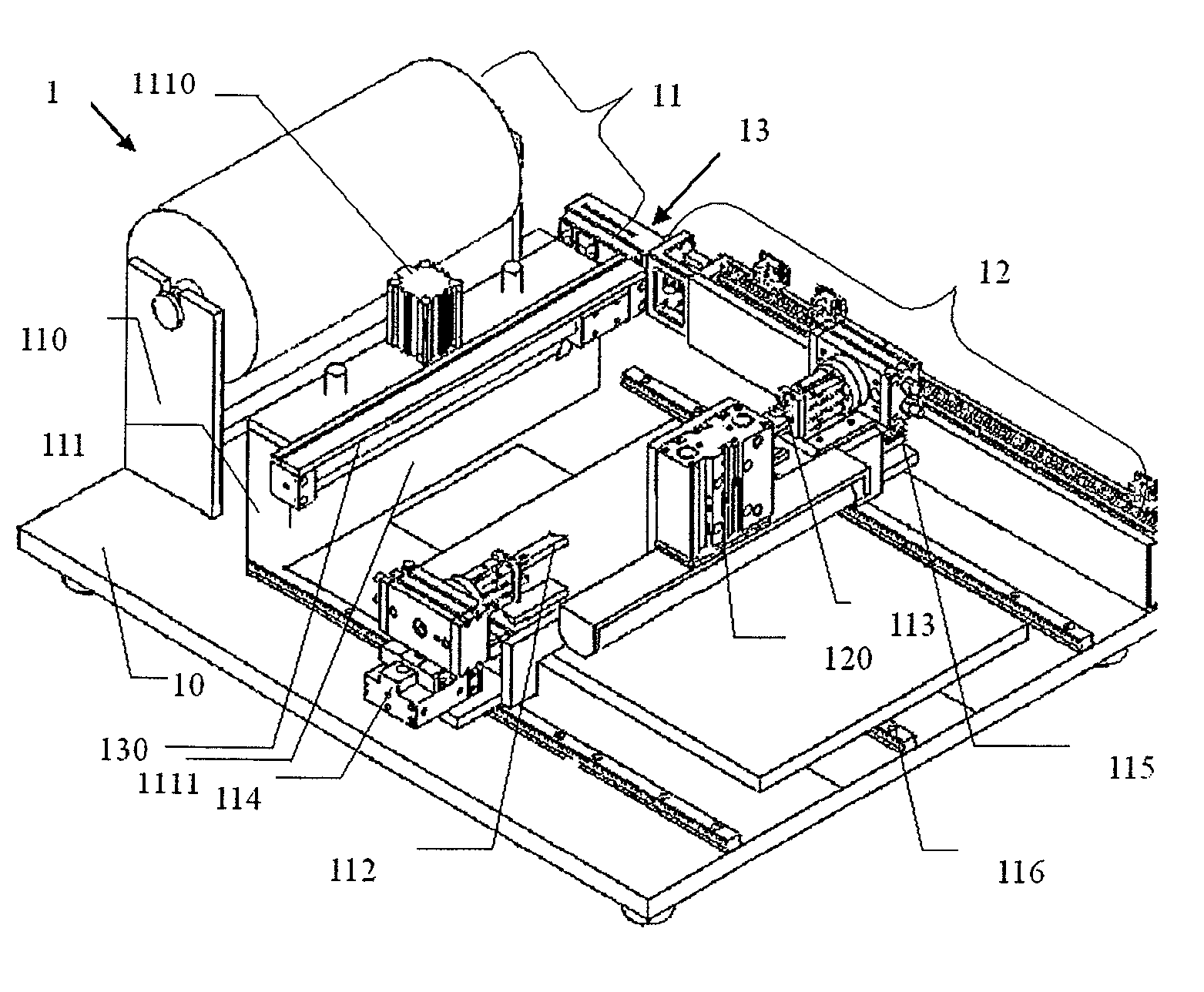
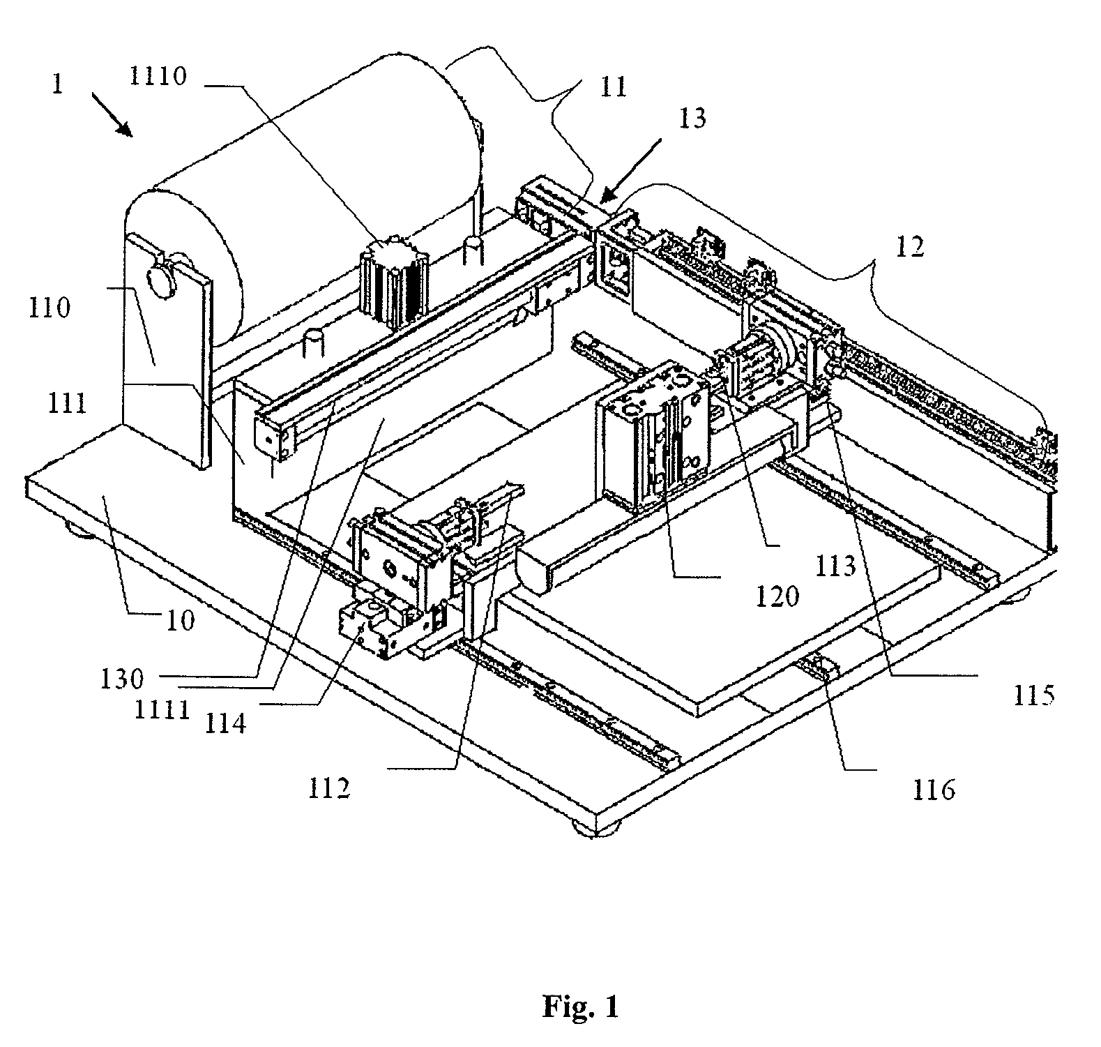
[0072]Embodiment 1 of the present invention provides a film coating apparatus, as shown in FIG. 1, comprising:

[0073]a feeding unit 11, an attaching unit 12 and a cutting unit 13, which are arranged on a base 10.

[0074]The feeding unit 11 is configured to feed a film to be attached onto the surface of a product, and configured to attach the film to a first side face and a second side face of the product. In this embodiment, the product is a light guide plate, a semi-finished backlight product or a finished backlight product.

[0075]The attaching unit 12 is connected to the feeding unit 11 and configured to attach the film to the surface of the product.

[0076]The cutting unit 13 is connected to the feeding unit 11 and configured to cut the film.

[0077]In this embodiment of the present invention, the film coating apparatus is described by taking light guide plates, semi-finished backlight products and finished backlight products to be coated with films manually in the prior art as objects t...

embodiment 2

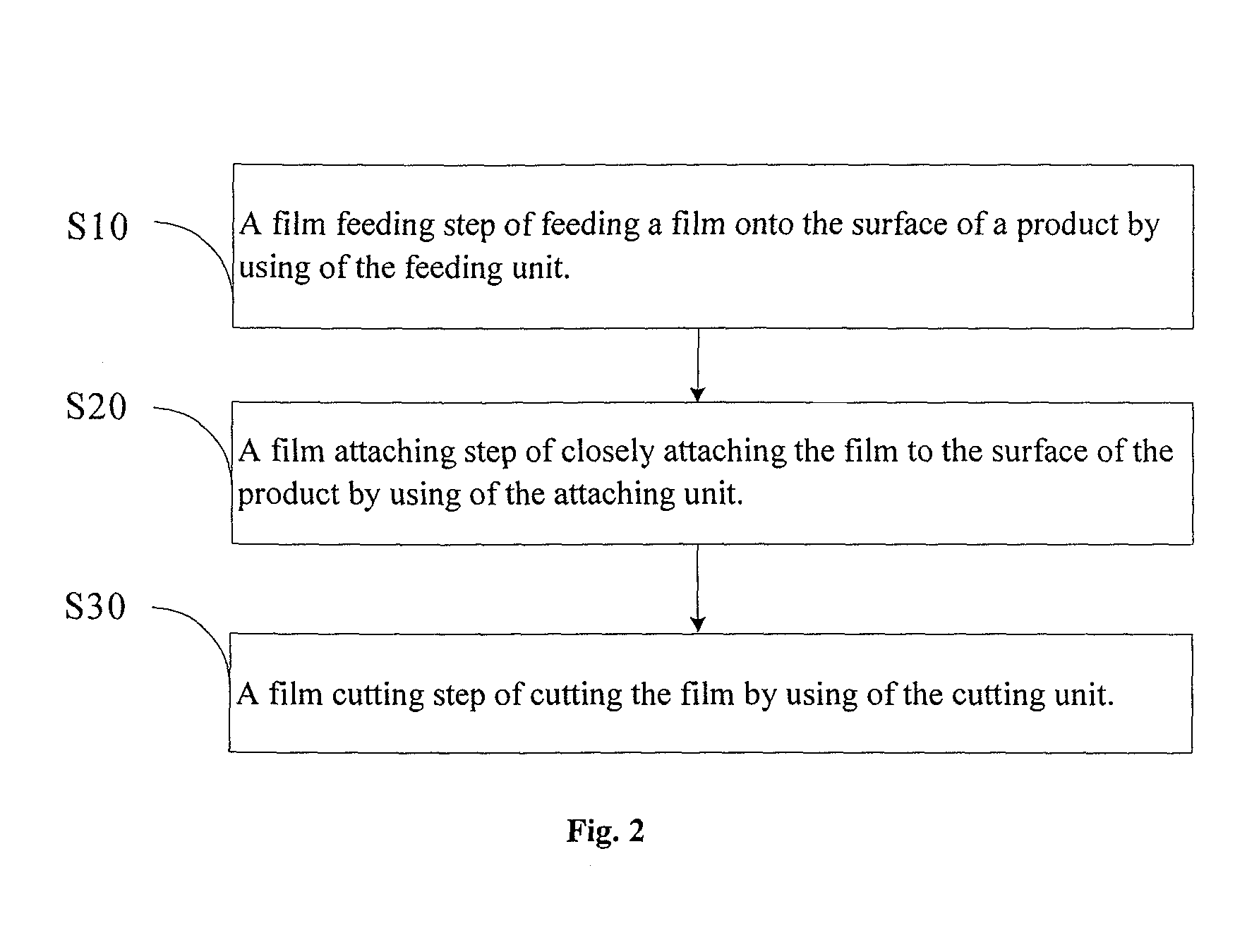
[0113]Embodiment 2 of the present invention provides a film coating method, as shown in FIG. 2, including:

[0114]step S10: a film feeding step of feeding a film onto the surface of a product by using of the feeding unit;

[0115]step S20: a film attaching step of closely attaching the film to the surface of the product by using of the attaching unit; and

[0116]step S30: a film cutting step of cutting the film by using of the cutting unit.

[0117]Preferably, the film feeding step in step S10 may specifically include the following steps S101-S103 as shown in FIG. 3.

[0118]step S101: The first rotatable clamp and the second rotatable clamp of the feeding unit clamp two ends of a first material end of the film, respectively, so that, starting from the first material end, the film is drawn out from the film storage unit of the feeding unit and then passes through the feeding assembly of the feeding unit.

[0119]It is to be noted that the first material end refers to the front end of the fed film w...


PUM

PropertyMeasurementUnit
rotation anglesaaaaaaaaaa
compressaaaaaaaaaa

Abstract

Embodiments of the present invention provide a film coating apparatus and a film coating method, relating to the field of manufacturing of display devices. The film coating apparatus comprises a feeding unit, an attaching unit and a cutting unit, which are arranged on a base, wherein the feeding unit is configured to feed a film to be attached to the surface of a product; the attaching unit is connected to the feeding unit and configured to attach the film onto the surface of the product; and the cutting unit is connected to the feeding unit and configured to cut the film. According to the present invention, the film coating of a light guide plate, a semi-finished backlight product and a finished backlight product can be achieved, the labor intensity of operators is greatly reduced, the productivity is liberated, and the production efficiency is further improved. Meanwhile, coating deviation resulted from human factors is avoided, and the bottleneck in the automation of producing TFT-LCDs is overcome.

Description

FIELD OF THE INVENTION[0001]The present invention relates to the field of manufacturing of display devices, in particular to a film coating apparatus and a film coating method.BACKGROUND OF THE INVENTION[0002]During the manufacturing of TFT-LCDs (Thin Film Transistor-Liquid Crystal Display), the production of backlight sources requires a completely dust-free production environment, and thus the requirement on the environment is quite high. To meet the above requirement, light guide plates, semi-finished backlight products and finished backlight products need to be coated with films before being stored and transported.[0003]In the existing production process, the film coating of a light guide plate, a semi-finished backlight product and a finished backlight product is completely accomplished manually. Even in some relatively advanced factories, the film coating is still accomplished manually with the aid of assistant tools. However, the manual film coating of a light guide plate, a s...

Claims


Application Information

Patent Timeline
Patent Type & Authority Patents(United States)
IPC IPC(8): B65H37/04B32B37/00B29C63/04B32B38/18B32B38/00B32B37/22
CPCB65H37/04B32B37/0046B32B38/1833B29C63/04B32B37/0053B32B37/22B32B38/0004B32B38/18B32B2457/202B65H2301/5162B65H2801/61Y10T156/1085Y10T156/12
Inventor GU, ZHENGHECAO, CHUNLEI
Owner BOE TECH GRP CO LTD
Learn More