Bilge pump and method

Active Publication Date: 2012-07-05
WALLACE WILLIAM L
View PDF2 Cites 10 Cited by
  • Summary
  • Abstract
  • Description
  • Claims
  • Application Information

AI Technical Summary

Problems solved by technology

The retention of bilge liquids on board a boat is highly undesirable, as it may contain hydrocarbons and/or other engine compartment liquids in addition to water.
Because they are in the very bottom of the boat, bilges are generally very difficult to access. and it generally is not practical to collect bilge liquids in a bucket or other container which may be carried through confined spaces and up ladders for disposal above deck.
Bilge pumps typically are unable to distinguish between environmentally safe and unsafe liquids and the discharge thereof into the waterways creates additional problems.
In addition to the purging of bilge liquid from the bilges, there are spills of liquids of various types below decks, e.g. an oil leak in a piece of machinery, fuel leaks, or the accidental overturn of a coffee pot.
Moreover, the seals of the pump must be moistened to prevent excessive wear and replacement, a task often difficult in the confined space of a bilge or the engine room compartment of a boat.
Installation of bilge pumps is often difficult due to the tight quarters of the engine compartment or bilge area.
Mounting the bilge pump to the hull, connecting the electrical wiring, and connecting the pump outlet to the drain conduit are all complicated by the confined working space.
Replacing an inoperable bilge pump may even be more difficult.
Replacement bilge pumps usually have a mounting footprint and overall configuration that is different from th

Method used


Image

  • Bilge pump and method
  • Bilge pump and method
  • Bilge pump and method

Examples


Embodiment Construction

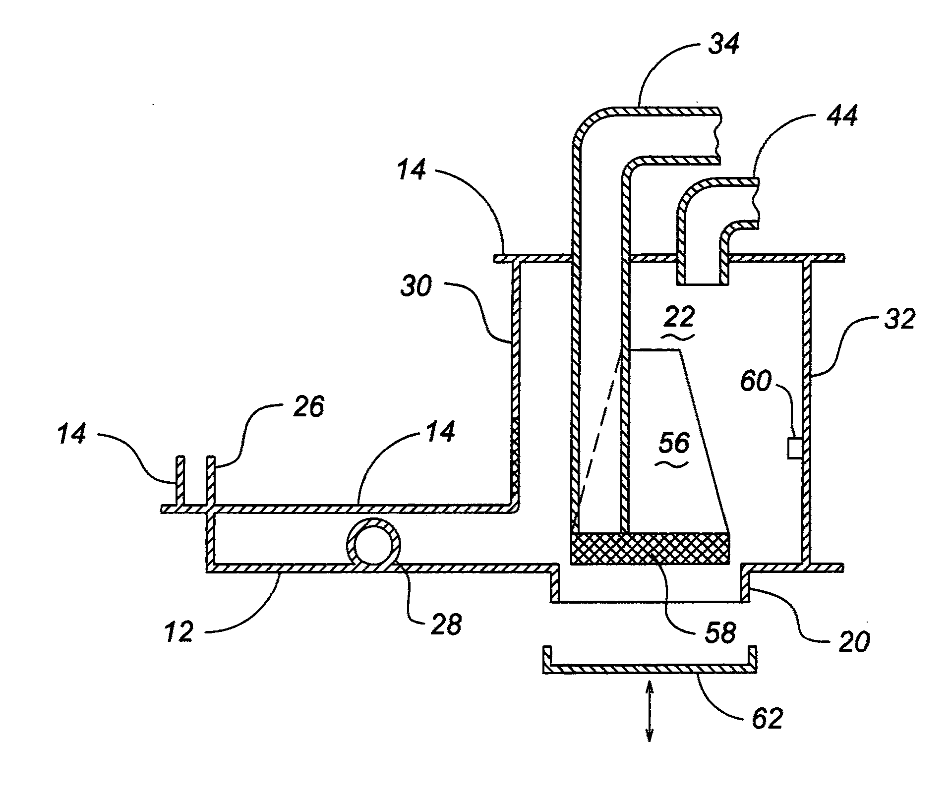
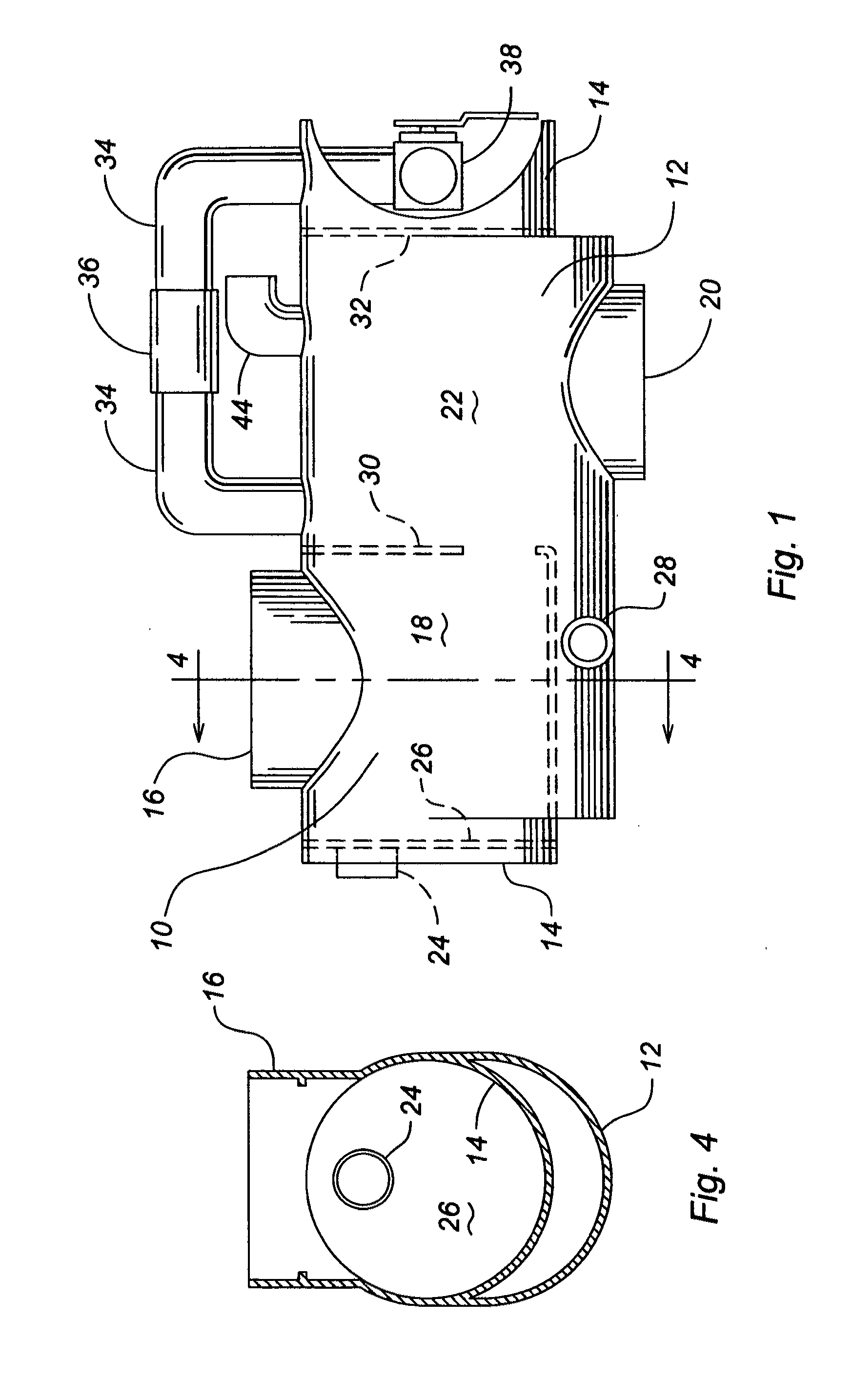
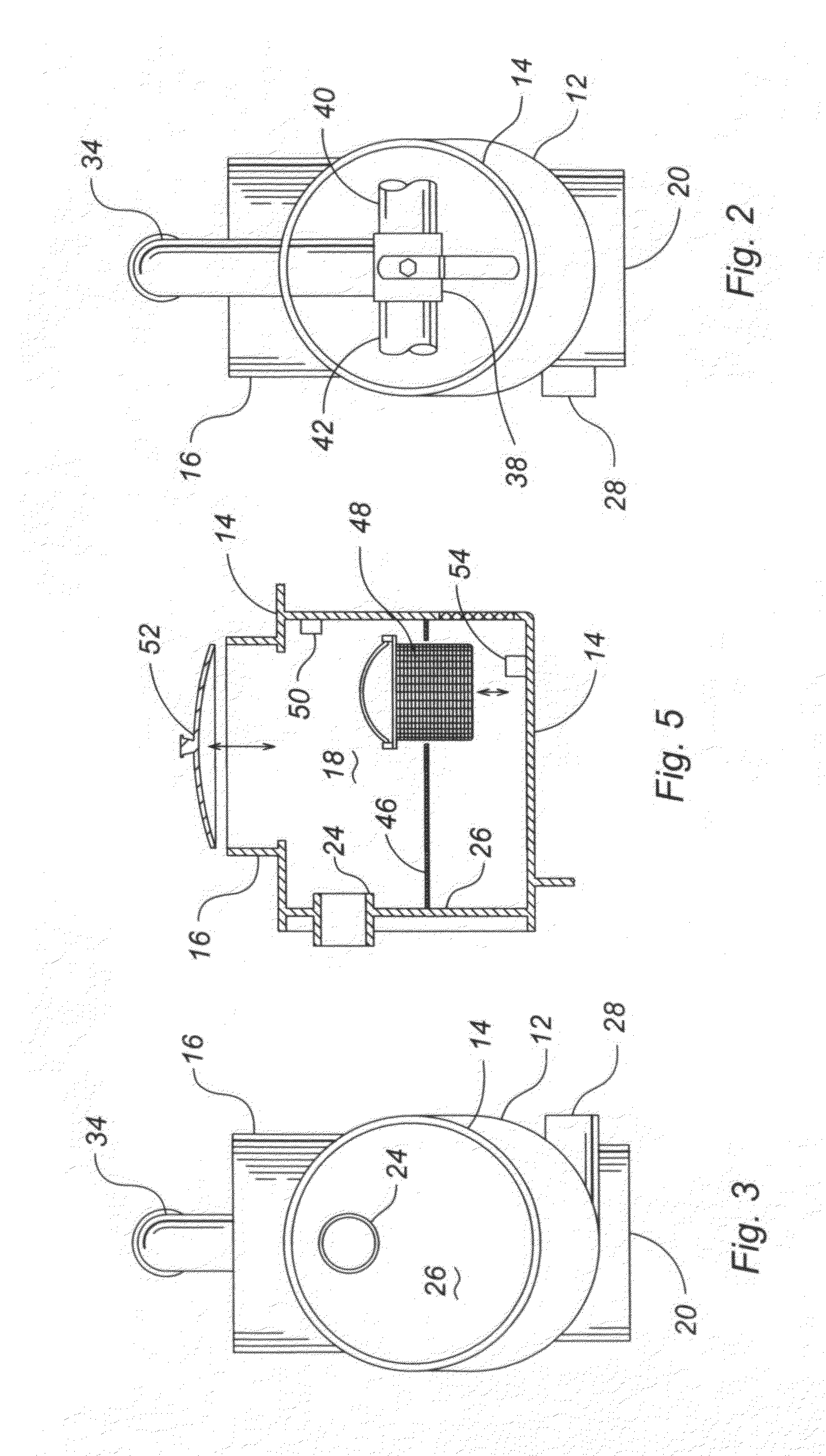
[0022]With reference to FIGS. 1-4 where like numerals have been used for like elements thereof, a preferred embodiment of the vacuum assisted bilge pump of invention is illustrated. The pump body may be molded but it has been found convenient to form the pump body from two sections, each approximately 8.5 inches in diameter, of a suitable non-corroding and electrically non-conducting pipe such as PVC or other plastic or fiberglass. The shorter section 12 is split through the longitudinal axis thereof and fused to the longer section 14 as illustrated. A cradle (not shown) may be provided to support the pump, and the pump may be integral with the cradle or removably mounted thereon. Movement of the cradle and pump may be facilitated by the use of conventional casters. (not shown)

[0023]A third section of pipe 16 approximately 7.25 inches in outside diameter is oriented vertically and is fused to the upper portion of section 14 adjacent the input or left end of the body 10, and the port...


PUM


Abstract

A vacuum assisted bilge pump small enough for the crowded spaces below decks in the engine and pump room of a boat which can also function as a transfer pump, a crash pump and a fire extinguisher. The pump comprises two chambers and is internally configured to aid in the separation of gas and liquid increasing pump throughput.

Description

FIELD OF THE INVENTION[0001]The present invention relates to bilge pumps, and more particularly to a vacuum assisted pump for pumping bilge fluids from a boat.BACKGROUND OF THE INVENTION[0002]Boats of any appreciable size have bilges where any liquid introduced into the boat collects under the force of gravity. These liquids may, e.g., be fresh or sea water, oil or gasoline from the propulsion system or on-board machinery, etc. Solids may also find their way into the bilge. Such combinations of liquids and solids will be referred to herein as “bilge liquids”. The retention of bilge liquids on board a boat is highly undesirable, as it may contain hydrocarbons and / or other engine compartment liquids in addition to water.[0003]There may be several bilges in a boat where bilge liquids may collect. Because they are in the very bottom of the boat, bilges are generally very difficult to access. and it generally is not practical to collect bilge liquids in a bucket or other container which ...

Claims


Application Information

Patent Timeline
IPC IPC(8): F04B53/20F04B49/00
CPCF04F3/00F04B53/20
Inventor WALLACE, WILLIAM L.
Owner WALLACE WILLIAM L
Why Eureka
Try Eureka