Gear pump

Active Publication Date: 2012-07-05
ROBERT BOSCH GMBH
View PDF9 Cites 2 Cited by
  • Summary
  • Abstract
  • Description
  • Claims
  • Application Information

AI Technical Summary

Benefits of technology

[0016]Further preference is given to the layer being designed with a projection, and therefore the stator bearing against an inner wall of the housing with a prestress. In particular, the layer is designed such that the prestress has the effect of pr

Problems solved by technology

However, mounting of the annular gear, which has to adopt the drive torque of the electric motor, is problematical in configurations of this kind.
The solutions known in the prior art for mounting

Method used


Image

  • Gear pump
  • Gear pump
  • Gear pump

Examples


Embodiment Construction

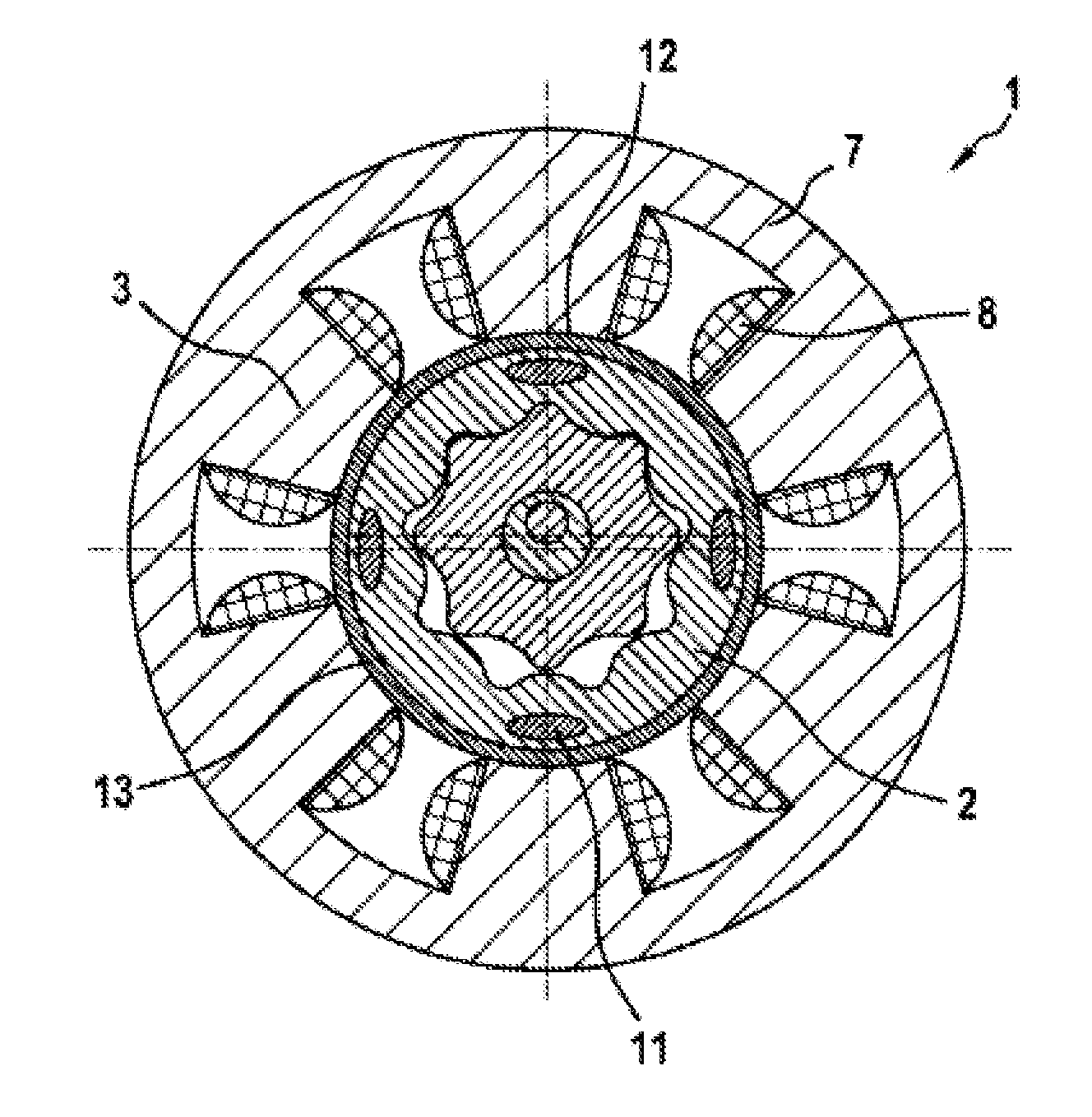
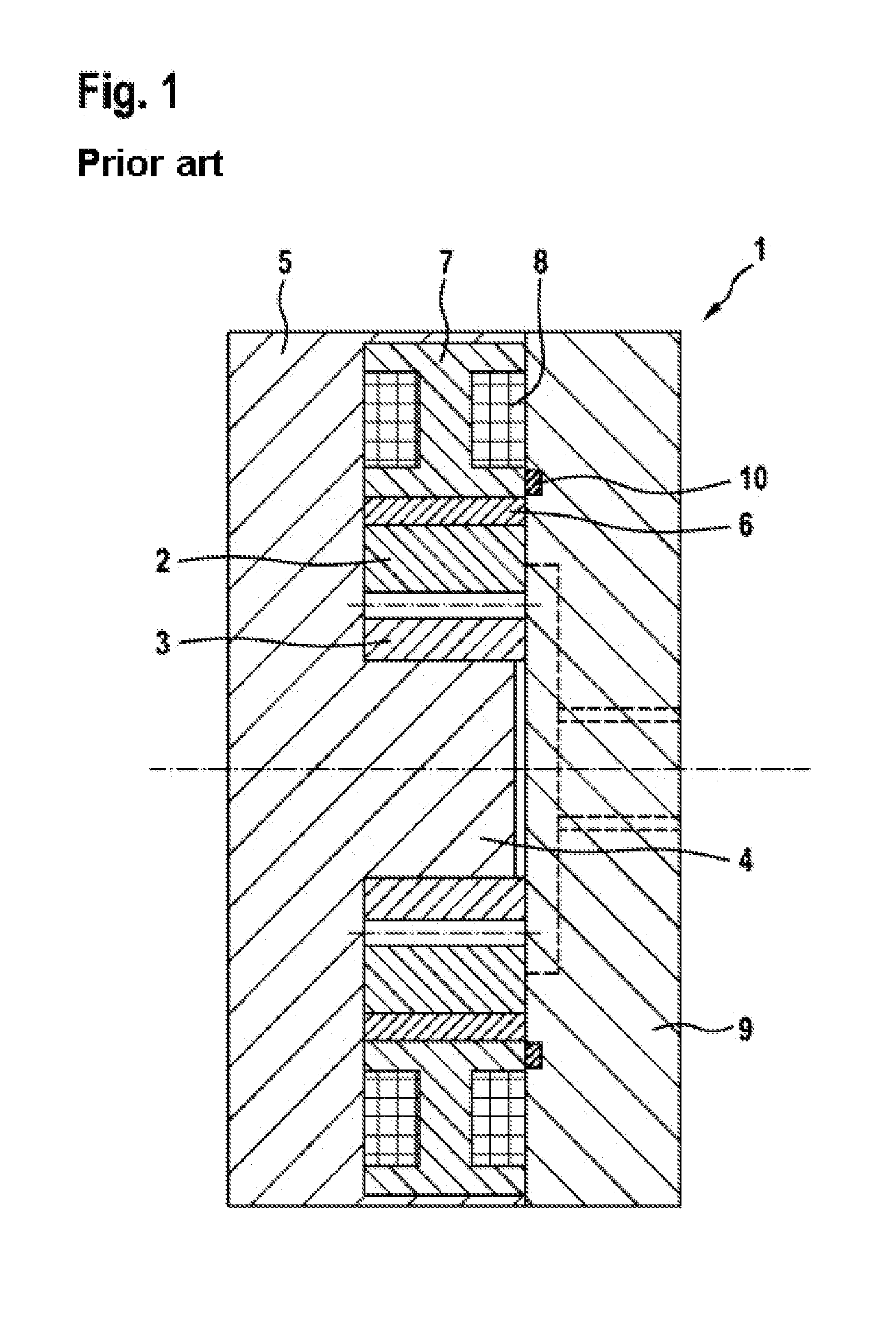
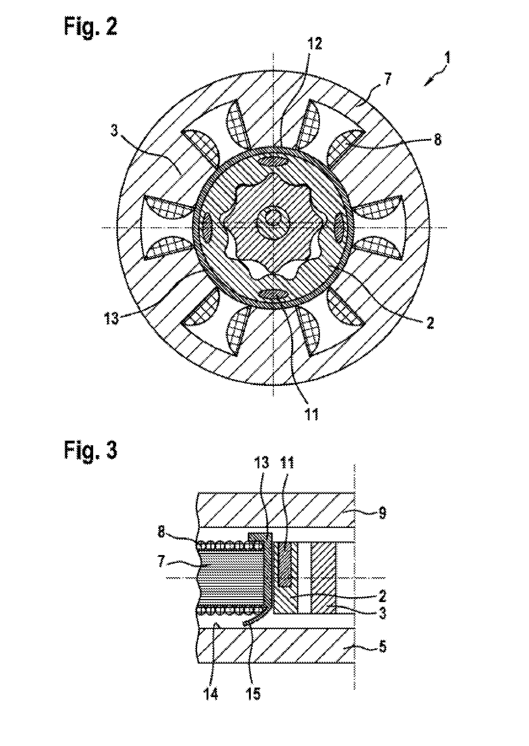
[0021]FIG. 1 shows a section though an internal gear pump 1 according to the prior art. The internal gear pump 1 comprises a pair of gearwheels which comprises an internally toothed annular gear 2 and an externally toothed gearwheel 3. The gearwheel 3 is arranged in a rotatable manner on a bearing pin 4 eccentrically with respect to the annular gear 2. If the annular gear 2 is made to rotate, the external tooth system of the gearwheel 3 meshes with the internal tooth system of the annular gear 2 and generates a volumetric delivery flow of the fluid, in which the tooth system runs. The pair of gearwheels comprising the annular gear 2 and the gearwheel 3 is arranged in a housing 5, with the bearing pin 4 being formed in one piece or integrally with the housing 5. Furthermore, the annular gear 2 is connected to an annular magnet 6 in a rotationally fixed manner, with the annular magnet 6 extending around the annular gear 2 in a radially encircling manner. The annular magnet 6 runs in a...


PUM


Abstract

The invention relates to a gear pump (1) for conveying a fluid, said gear pump comprising a rotatably mounted, external geared toothed wheel (3) and an internal geared annular gear (2) that are meshed in order to generate a conveying action, and are arranged together with an electrically commutable stator (7) in a housing (5). The stator (7) extends concentrically around the annular gear (2) and interacts with the annular gear to generate an electromotive force. The annular gear (2) has a closed, homogeneous cylindrical surface and a plain bearing (13) is provided on the stator (7).

Description

BACKGROUND OF THE INVENTION[0001]Rotary screw pumps comprise, amongst other things, internal gear pumps and annular gear pumps in which a driving gearwheel runs eccentrically in the internal tooth system of an annular gear. Internal gear pumps, which are particularly suitable for providing high pressures, are used to deliver fluids, for example to deliver fuel to an internal combustion engine.[0002]In the prior art, it is known to integrate internal gear pumps or annular gear pumps in an electronically commutated electric motor, with the rotor of the electric motor simultaneously being in the form of an annular gear of the internal gear pump or annular gear pump.[0003]DE 10 2006 007 554 A1 describes a delivery pump which is integrated in an electric motor. The delivery pump comprises a first gearwheel and a second gearwheel. A delivery space is formed between the two gearwheels. The second gearwheel is mounted at its centre on a mandrel. The first gearwheel is an external gearwheel ...

Claims


Application Information

Patent Timeline
IPC IPC(8): F04C2/10
CPCF04C2/086F04C2/102F04C2230/22F04C15/008F04C11/008F04C2240/56
Inventor FRANK, JOSEFFUCHS, ALEXANDERORTNER, KLAUS
Owner ROBERT BOSCH GMBH
Why Eureka
Try Eureka