E-Band radio transceiver architecture and chip set

a technology of front-end transceivers and chip sets, applied in electrical equipment, telephonic communication, substation equipment, etc., can solve the problems of increasing complexity and consuming circuit area, and achieve the effect of high performance and cost-effectiveness

Active Publication Date: 2005-08-04
NORTHROP GRUMMAN SYST CORP
View PDF47 Cites 29 Cited by
  • Summary
  • Abstract
  • Description
  • Claims
  • Application Information

AI Technical Summary

Benefits of technology

[0014] According to an exemplary embodiment of the present invention, a MMIC-based radio front-end architecture in E-Band is disclosed which provides high performance in a cost effective solution for a broad range of applications.
[0015] In particular, a gallium arsenide (GaAs) MMIC-based transceiver integrated chip set is provided for E-Band applications comprising three very highly integrated monolithic microwave integrated circuit (MMIC) devices. In a preferred embodiment two of the devices are fabricated in a pseudo-morphic high electron mobility transistor (p-HEMT) process and one of the devices is fabricated in an ion-implanted MESFET device to reduce the cost of the overall chip set in volume applications. In another embodiment all three devices utilize the p-HEMT process to keep the chip set common to a single process technology. Since the chip set is highly integrated, many of the aforementioned disadvantages of the known prior art E-Band chip sets are overcome. In particular, since the present invention E-band front-end transceiver chip set is specifically designed and optimized with respect to manufacturing the most compact upper millimeter wave transceiver chip set possible, part count and manufacturing costs are reduced, while performance is maximized. As a result, the present invention makes up one of the most compact upper millimeter wave transceiver chip sets in the industry.
[0016] The incorporation of filtering in monolithic media has uniqueness in that it is not normally combined on the integrated circuit itself, but often times realized in other thin film or discrete circuit media, which adds complexity and consumes circuit area. With the present invention, the filtering is partially combined into the matching networks of associated amplifier stages to form “bandpass” amplifiers. The generation of the LO signal and conversion from the first intermediate frequency to baseband can be realized using a lower cost, higher yield, ion-implanted GaAs metal semiconductor field effect transistor (MESFET) process. This is unique because most millimeter wave chip sets are fabricated strictly in a more costly epitaxial type HEMT process.

Problems solved by technology

The incorporation of filtering in monolithic media has uniqueness in that it is not normally combined on the integrated circuit itself, but often times realized in other thin film or discrete circuit media, which adds complexity and consumes circuit area.

Method used


Image

  • E-Band radio transceiver architecture and chip set
  • E-Band radio transceiver architecture and chip set
  • E-Band radio transceiver architecture and chip set

Examples


first exemplary embodiment

of the Present Invention

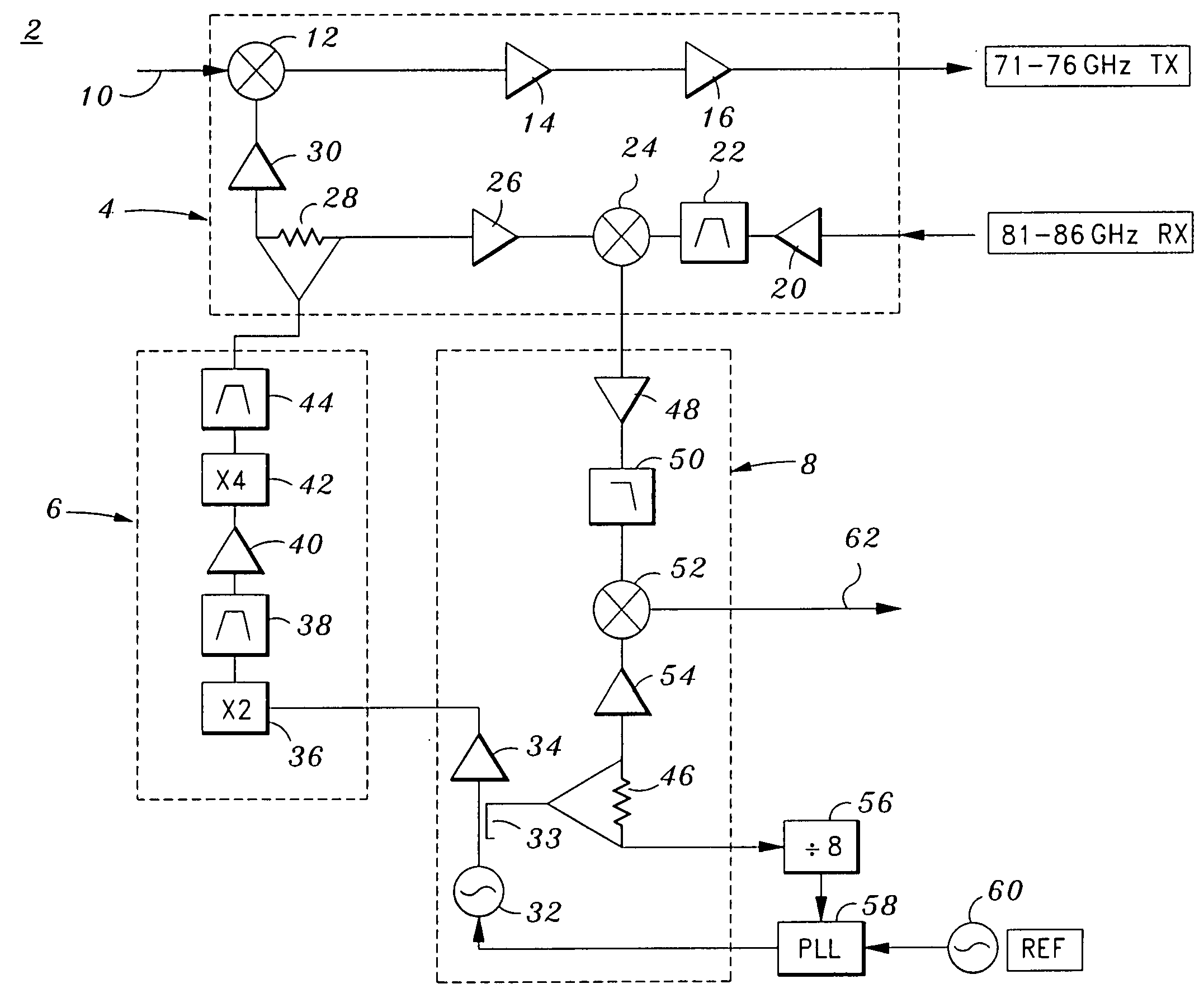
[0044] According to a first exemplary embodiment of the present invention, a MMIC-based radio front-end and architecture thereof for E-Band applications which comprises a chip set including three MMIC devices, 6, 8, 10 is disclosed as the circuit depicted in FIG. 1. Unique to the first embodiment of the present invention is a fundamental up and down converter mixing scheme. Each MMIC device 6, 8, 10 is now herein described below.

First MMIC Device: Transmitter and Receiver Chip

[0045] A first exemplary MMIC device 4 is [also referred to as the transmitter (TX) and receiver (RX) chip] is provided which includes as many as nine circuit functions on a single chip, including a fundamental mixer 12 (or modulator), transmission amplifier 14, transmission amplifier 16, amplifier 20, bandpass filter 22, fundamental mixer 24 (or modulator), amplifier 26, power divider 28, and amplifier 30. The MMIC device 4 has three circuits, including a transmission circuit (12, 14...

second exemplary embodiment

of the Present Invention

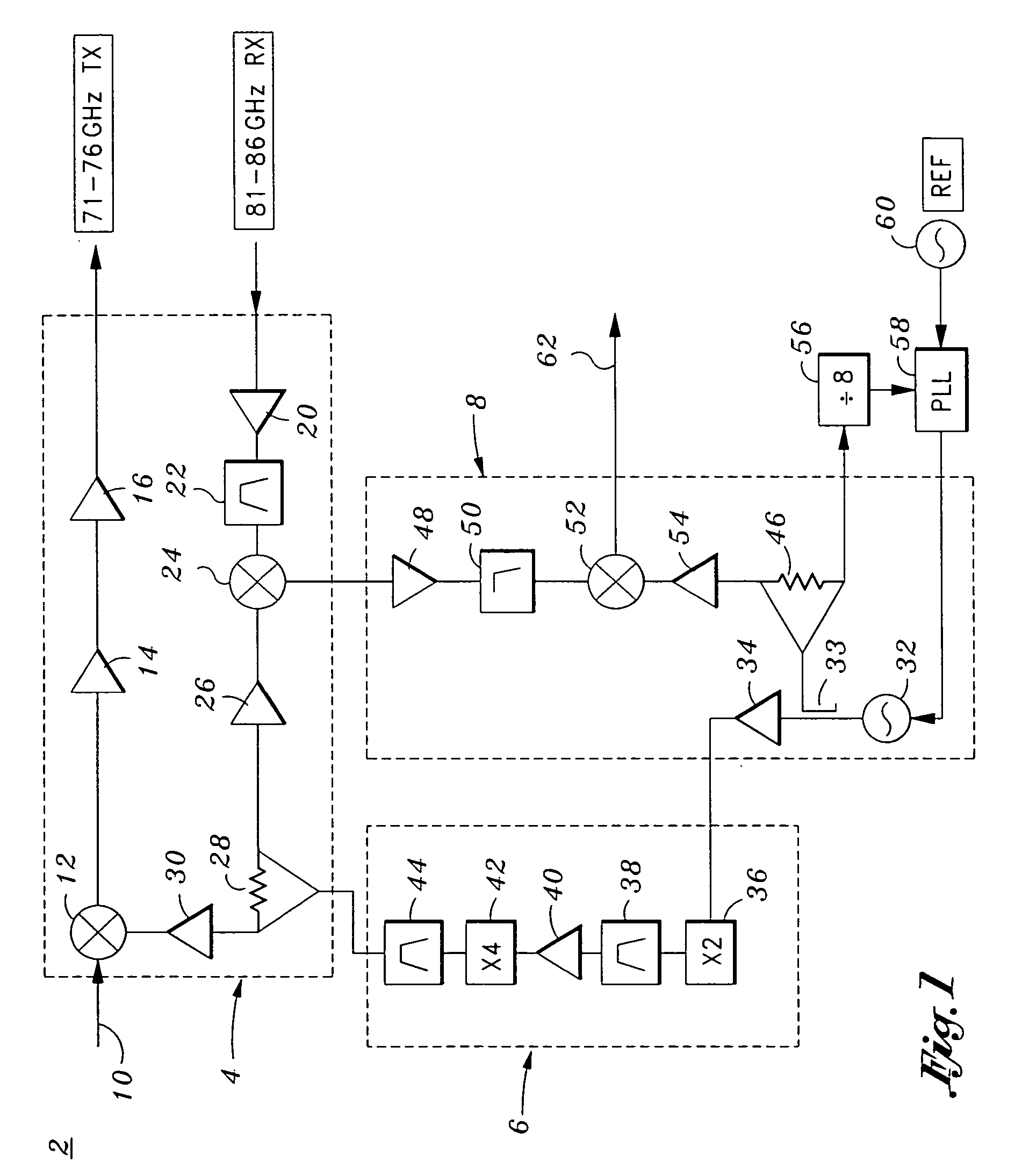
[0054] According to a second exemplary embodiment of the present invention, a MMIC-based radio front-end and architecture thereof for E-Band applications which comprises a chip set 3 including three MMIC devices, 5, 7, 8 is disclosed as the circuit depicted in FIG. 2. The second embodiment of the present invention employs a sub-harmonic mixing scheme by eliminating a multiplier circuit in the multiplier chain chip 7 (or second MMIC device 7), and by furthermore, utilizing singly balanced sub-harmonic mixers in the transmitter and receiver chip 5 (or first MMIC device 5).

[0055] In particular, in the second exemplary embodiment of the present invention, the second MMIC device 7 does not include the X2 multiplier 36 or bandpass filter 38. The X2 multiplier 36 and bandpass filter 38 may be omitted to provide a sub-harmonic mixing scheme to be used in mixers 13 and 25 in the first MMIC device 5. Eliminating multiplier 36 simplifies the local oscillator generation...

third exemplary embodiment

of the Present Invention

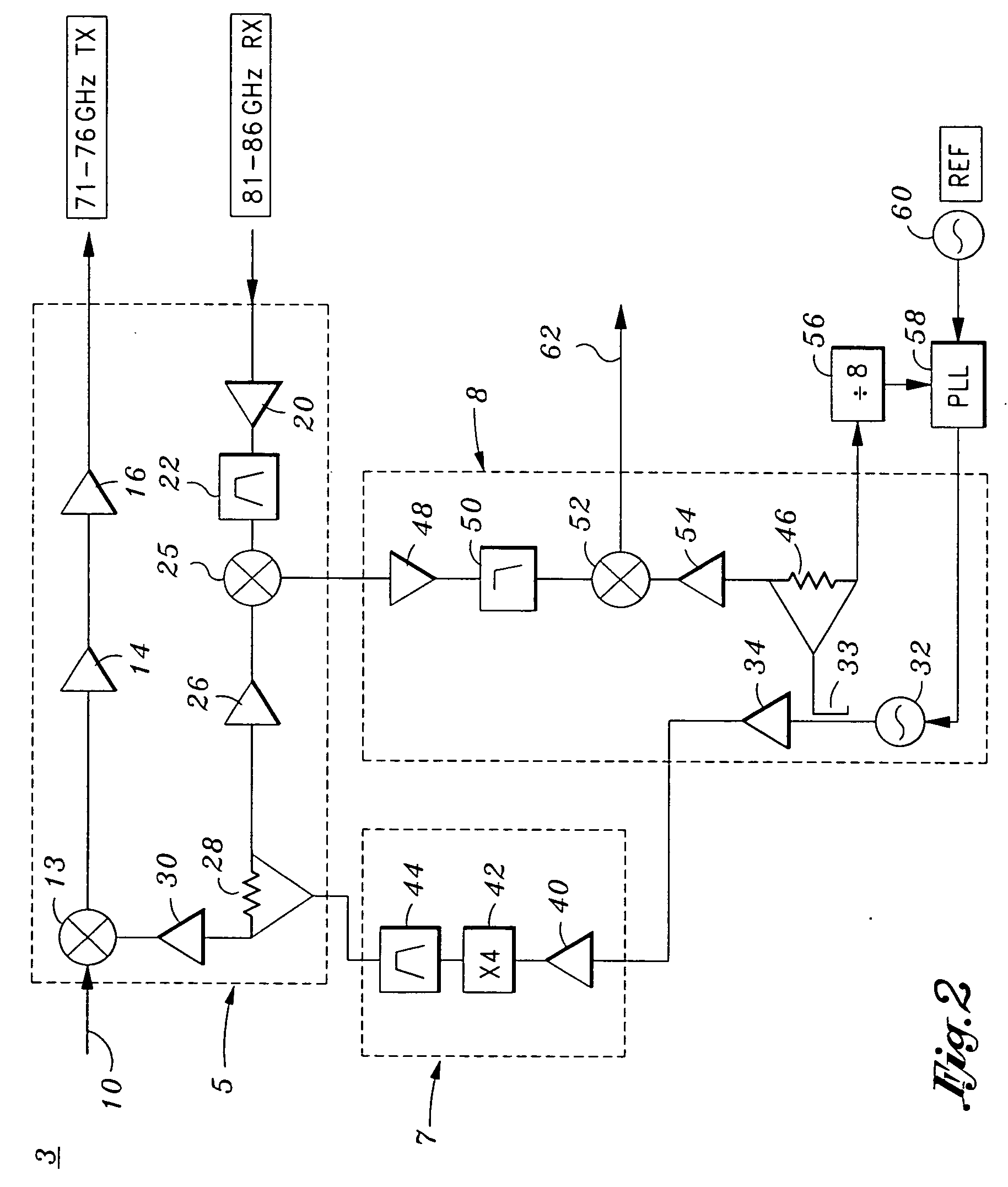
[0066] According to a third exemplary embodiment of the present invention, a MMIC-based radio front-end and architecture thereof for E-Band applications which comprises a chip set 11 including two MMIC devices 5, 9 is disclosed as the circuit depicted in FIG. 3. The third embodiment of the present invention is similar to that of the second embodiment in that it employs a sub-harmonic mixing scheme by eliminating a multiplier circuit in the multiplier chain chip 7 (see second MMIC device 7 from FIG. 2), and by furthermore, utilizing singly balanced sub-harmonic mixers in the transmitter and receiver chip 5 (or first MMIC device 5).

[0067] In particular, in the third exemplary embodiment of the present invention, the X4 multiplier and bandpass filter 44 are integrated onto a second MMIC device 9, while the amplifier function 40 is combined with buffering amplifier 34 also on the second MMIC device 9. As a result, the second MMIC device 7 from the second embodim...


PUM


Abstract

A GaAs E-Band transceiver front-end chip set is provided comprising three MMIC devices. The first device includes a circuit for receiving data at baseband, mixing the data with an LO signal having an E-Band frequency, and transmitting a resultant data stream at an upconverted E-Band frequency; a circuit for receiving data having an E-Band frequency, mixing the received data with an LO signal having an E-Band frequency, and downconverting the resultant mixed received signal to an IF; and a circuit for dividing a received LO signal at an E-Band frequency and communicating the LO signal to the transmission and receiver circuits. The second device comprises a circuit for receiving an LO signal at a reference frequency, and multiplying the LO signal to an E-Band frequency. The third device comprises a circuit for mixing the mixed received IF signal with an LO signal, and downconverting the resultant mixed received signal to a baseband frequency, and a circuit for generating an LO signal, communicating the LO signal to the second device, coupling the LO signal, dividing the coupled LO signal, and communicating the divided LO signal to the second downconversion circuit. The first and second devices may be manufactured by a p-HEMT process and the third device is manufactured by a MESFET process. Additionally, an E-Band communications system is provided which utilizes the aforementioned chip set.

Description

CROSS-REFERENCE TO RELATED APPLICATIONS [0001] Not Applicable STATEMENT RE: FEDERALLY SPONSORED RESEARCH / DEVELOPMENT [0002] Not Applicable BACKGROUND OF THE INVENTION [0003] 1. Field of the Invention [0004] The present invention relates to radio front-end transceiver architecture and packaging. In particular, the present invention relates to a gallium arsenide (GaAs) MMIC-based front-end transceiver integrated chip set for E-Band applications. [0005] 2. Background of the Invention [0006] The present application is directed to “millimeter wave” frequencies which generally comprise frequencies above 40 GHz. In particular, there has been a tremendous interest in utilizing the E-Band portion of the electromagnetic spectrum because of the inherently wide bandwidth available in the E-band frequency range. [0007] E-Band (also sometimes referred to as W-Band) is defined by the FCC as frequency ranges 71-76 GHz, 81-86 GHz and 92-95 GHz. The FCC has set aside E-band primarily for commercial u...

Claims


Application Information

Patent Timeline
Patent Type & Authority Applications(United States)
IPC IPC(8): H04B1/38H04B1/40H04B1/44
CPCH04B1/408H04B1/18
Inventor CONSOLAZIO, STEPHEN JAMES
Owner NORTHROP GRUMMAN SYST CORP
Why Eureka
Try Eureka