Cooling device for an electronic component

a technology for electronic components and cooling devices, which is applied in the direction of indirect heat exchangers, light and heating apparatuses, laminated elements, etc., can solve the problems of increasing the number of switching events over time per device, the migration to smaller design processes, and the inability to keep up with the increasing complexity of faster integrated circuits. , to achieve the effect of uniform cross sectional area, avoiding bottlenecks, and rapid removal of hea

Inactive Publication Date: 2008-05-22
NYTELL SOFTWARE LLC
View PDF19 Cites 29 Cited by
  • Summary
  • Abstract
  • Description
  • Claims
  • Application Information

AI Technical Summary

Benefits of technology

[0016]The cooling device as recited above targets the immediate removal of a liquid heated by a heat source away from the heat source, and its distribution throughout a hierarchical channel system in the device. Outbound and inbound groups of channels are spatially separated in order to avoid thermal exchange between the groups of channels that would undesirably create a rete mirabile effect. Throughout the channel system, a substantially uniform cross sectional area of each generation of branches is maintained, thereby avoiding bottlenecks that would negatively impact the efficacy of the pump used to circulate the fluid and result in flow asymmetries.
[0017]In view of the above, advantages of the present invention include rapid removal of heat from a heat source, separation of cooler (inbound) and hotter (outbound) fluid channels, fractal arborization of channels for efficient area coverage, and maintenance of overall channel cross-sectional area through all generations of branching. The invention also offers the capability of a cost-effective cooling solution because of the capability of employing inexpensive materials, and good scalability into large-scale cooling devices.

Problems solved by technology

Cooling of electronic devices has become increasingly challenging as electronics have evolved.
As manufacturing processes are constantly refined, the migration to smaller design processes and the incumbent reduction in operating voltage has not kept pace with the increased complexity of faster integrated circuits (ICs).
Increasing number of transistors in combination with increasing operating frequencies has resulted in higher numbers of switching events over time per device.
As a result, within the same market space and price range, ICs are becoming more and more sophisticated and power-hungry with every generation.
Consequently, area power densities have increased, resulting in smaller dies dissipating higher thermal load.
As a result, formerly sufficient, passive heat spreaders and coolers often do not provide adequate cooling.
While sophisticated fin designs and powerful fans increase the active surface area useable for offloading thermal energy to the environment, even extremely well designed coolers are hitting inherent limitations.
In particular, significant limitations stem from the bottleneck of limited heat conductivity of the materials used, and specifically the fact that passive heat transfer throughout a solid structure is limited by the coefficient of thermal conductivity (CTE) of the material and the cross sectional area of the structure.
Therefore, even the most highly conductive material will not be able to maintain an even temperature distribution across the entire surface of the cooling device.
Any gradient, on the other hand, will cause a decrease in cooling efficiency since the temperature difference (ΔT) between the cooler's surface and the environment is the primary limiting factor for thermal dissipation to the surrounding.
In electronic devices, liquid cooling is still only marginally accepted for reasons that include the inherent risk of spills, cost overhead, and complexity of the installation, which involves routing of tubing and installation of radiators.
If the channels are too wide, laminar flow can cause a decrease in efficacy of heat exchange between the fluid and the device.
One often overlooked problem with a nondescript microchannel system is that the hydraulics are poorly defined.
If a pump simply pumps the fluid through the interstitial space without further routing in the form of macrochannels, then the centrifugal movement of the fluid can easily interfere with the centripetal flow that recycles the fluid back to the pump.
However, in the case of a cooling apparatus, such an effect is highly undesirable since heat would be trapped at its source despite all fluid movement.
Consequently, it appears highly disadvantageous in a heat exchange apparatus to have flow and counter flow in immediate proximity, especially if the septum between outgoing and incoming channels is thermally conductive.
However, these methods do not describe in any detail the geometry of the fluid circulatory system.

Method used


Image

  • Cooling device for an electronic component
  • Cooling device for an electronic component
  • Cooling device for an electronic component

Examples


Embodiment Construction

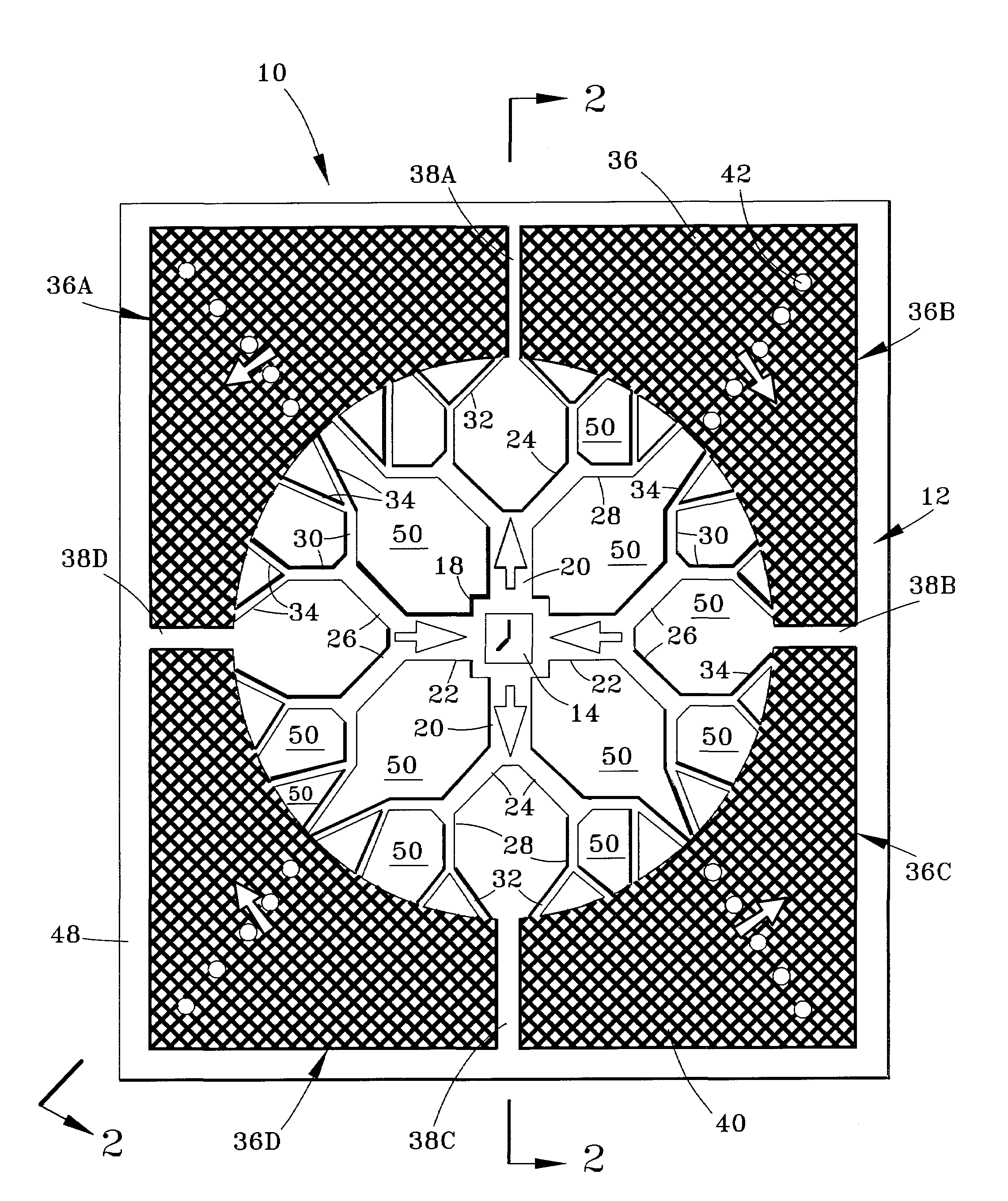
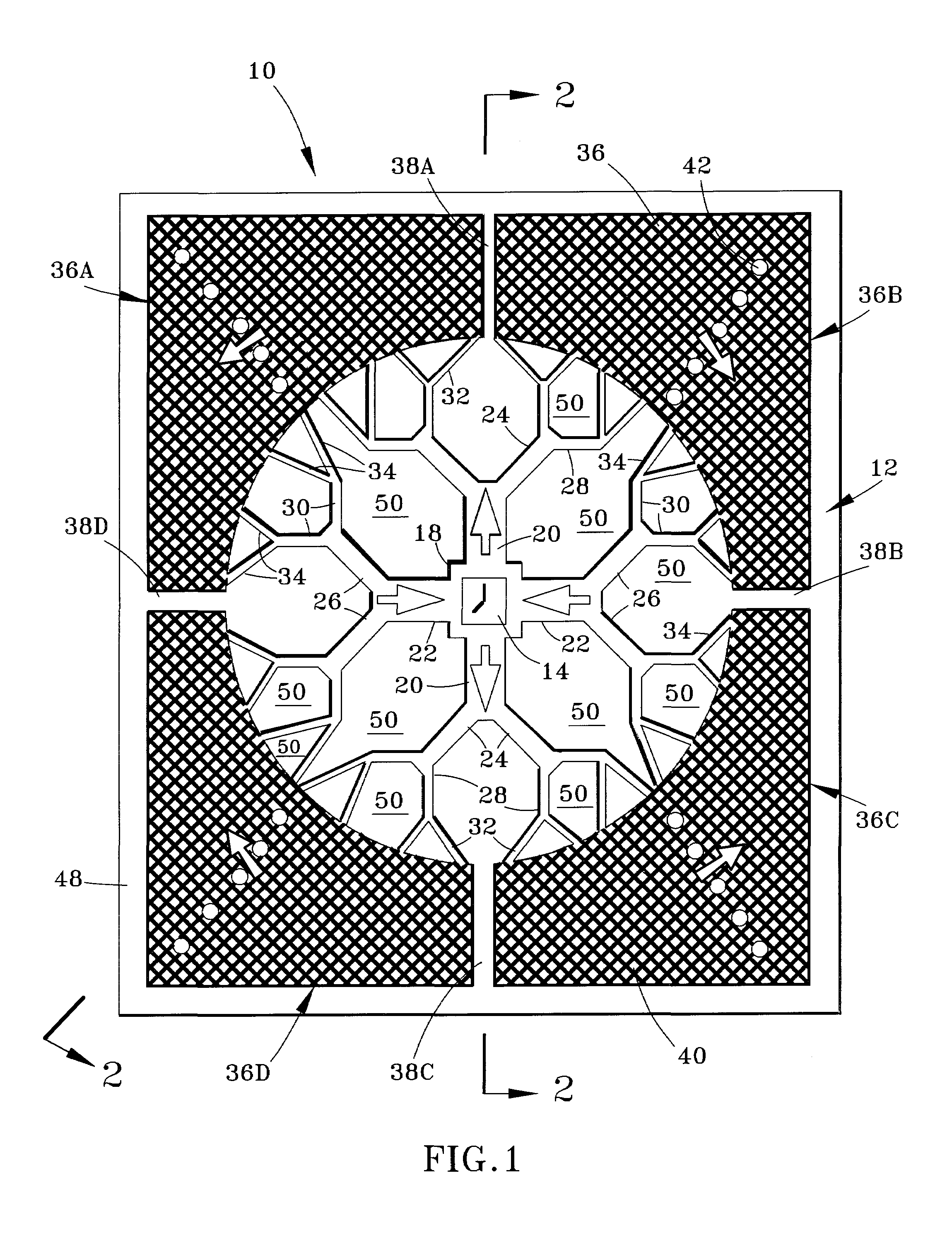
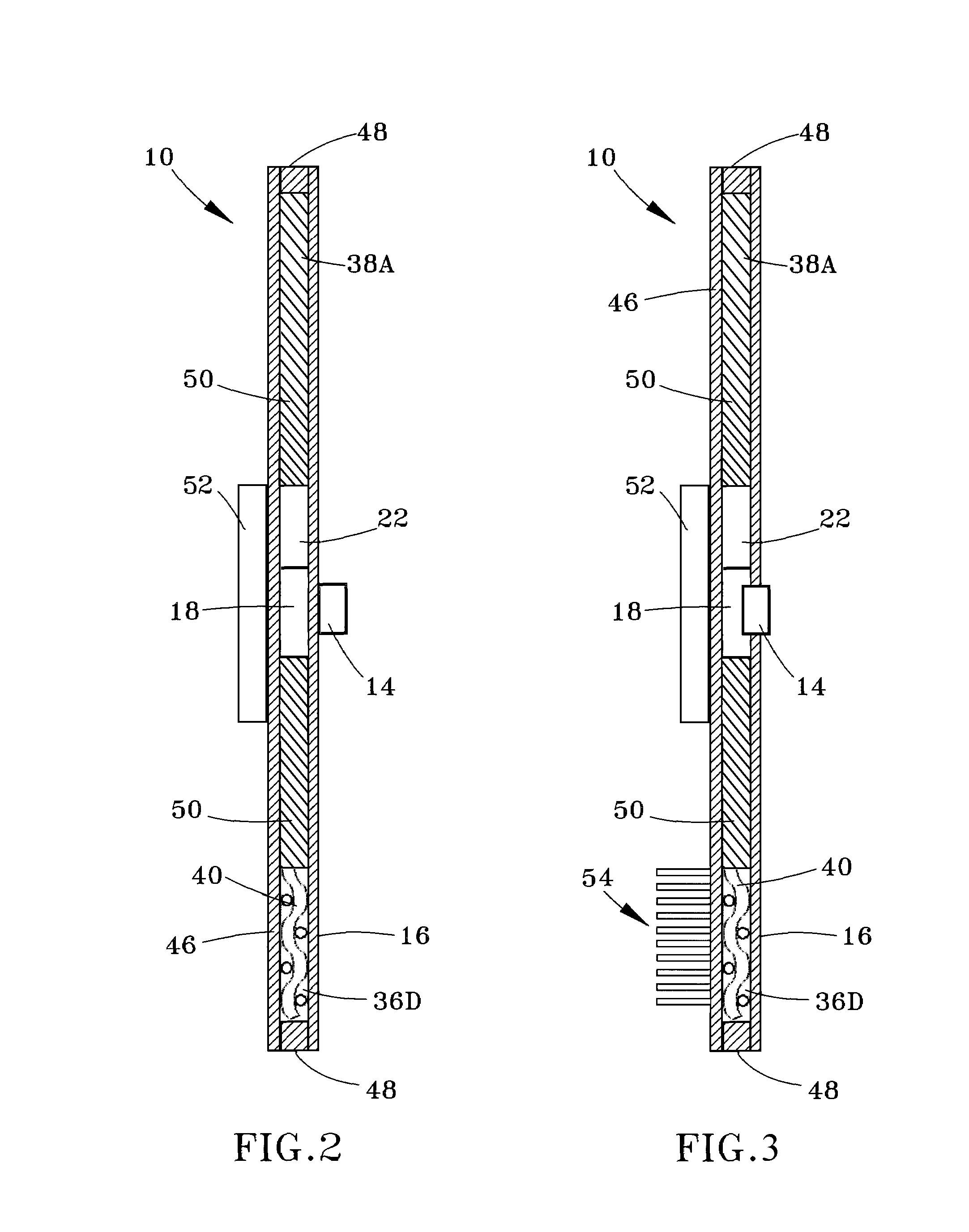
[0022]FIG. 1 shows a schematic overview of a channel system 12 defined in a cooling plate 10 adapted for cooling a semiconductor device 14. The location of the device 14 relative to the channel system 12 is superimposed in FIG. 1, though it is to be understood that the device 14 is not required to be located within the channel system 12. Instead, the device 14 may be limited to contact with an outer wall 16 (FIG. 2) of the cooling plate 10 that encloses the channel system 12 and separates the channel system 12 from the device 14, or may be partially inserted into the channel system 12 through the wall 16 (FIG. 3). The channel system 12 is delimited by the outer wall 16 and a base wall 46 (FIGS. 2 and 3), as well as structures 38A-38D, 48, and 50 between the outer and base walls 16 and 46, as discussed in more detail below. The channel system 12 can be defined in the base wall 46 of the plate 10, such as by etching the base wall 46, or can be patterned in a layer sandwiched between t...


PUM


Abstract

A cooling device for cooling an electronic component. The device has an enclosure adapted to contain a liquid coolant. The enclosure has an internal channel system comprising a cavity adjacent the electronic component, a first group of arborizing channels adapted to carry the liquid coolant away from the cavity, a second group of arborizing channels adapted to carry the liquid coolant to the cavity, and a plenum fluidically connecting the first and seconds groups of arborizing channels. Each group of arborizing channels has a parent branch and multiple successive sets of daughter branches with successively smaller cross-sectional areas, wherein the sum of the cross-sectional areas of the daughter branches of any set is approximately the same as that of its parent branch. Distal sets of the daughter branches are most distant from the cavity, fluidically connected to the plenum, and have the smallest cross-sectional areas of the daughter branches.

Description

CROSS REFERENCE TO RELATED APPLICATIONS[0001]This application claims the benefit of U.S. Provisional Application No. 60 / 866,140, filed Nov. 16, 2006, the contents of which are incorporated herein by reference.BACKGROUND OF THE INVENTION[0002]The present invention generally relates to cooling systems for electronic components. More particularly, this invention relates to a sealed cooling device with enhanced thermal management capabilities.[0003]Cooling of electronic devices has become increasingly challenging as electronics have evolved. As manufacturing processes are constantly refined, the migration to smaller design processes and the incumbent reduction in operating voltage has not kept pace with the increased complexity of faster integrated circuits (ICs). Increasing number of transistors in combination with increasing operating frequencies has resulted in higher numbers of switching events over time per device. As a result, within the same market space and price range, ICs are ...

Claims


Application Information

Patent Timeline
Patent Type & Authority Applications(United States)
IPC IPC(8): F28D15/00
CPCF28D15/00F28F3/06F28F3/12F28F2210/02H01L2924/0002H01L23/473H01L2924/00
Inventor SCHUETTE, FRANZ MICHAEL
Owner NYTELL SOFTWARE LLC
Why Eureka
Try Eureka