Fixturing member and device for permitting mixing in a pen injector

a technology of fixing member and injector, which is applied in the direction of liquid handling, packaging goods, food preparation, etc., can solve the problems of difficult control accuracy, device drawbacks, and difficult use of syringes for self-administration, and achieve the effect of facilitating the mixing of substances

Active Publication Date: 2012-07-05
BECTON DICKINSON & CO
View PDF1 Cites 15 Cited by
  • Summary
  • Abstract
  • Description
  • Claims
  • Application Information

AI Technical Summary

Benefits of technology

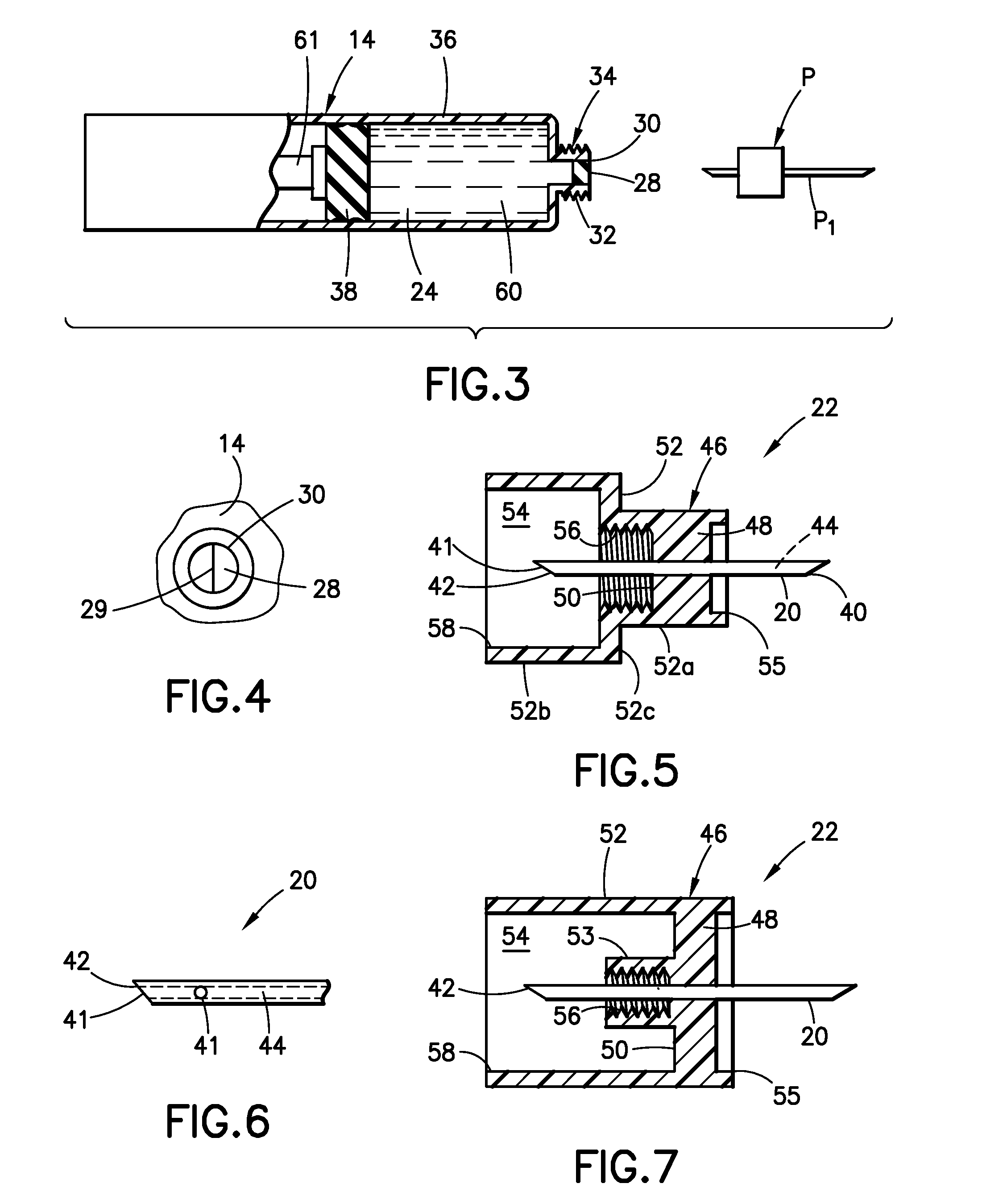
[0007]In one aspect, a fixturing member for fixing a source of flowable material relative to a pen injector so as to permit introduction of the flowable material into the pen injector is provided herein. The fixturing member includes a body having a web with opposing proximal and distal faces. A distal wall extends distally from the distal face of the web, with the distal wall at least partially encompassing a distal chamber. Features are formed on the body for removable mounting onto a pen injector. Also, features are formed on the body for mounting onto a source of flowable material. A cannula extends through the web, the cannula having proximal and dist

Problems solved by technology

Dose size, where less than the entire dose of the mixed substance is required, may be difficult to control accurately.
In addition, a syringe is a one-time use device which can not be used for multiple doses over time.
Syringes arc difficult to use for self-administration.
These devices also suffer drawbacks.
These containers must be specifically configured for mixing and, typically, are more expensive to

Method used


Image

  • Fixturing member and device for permitting mixing in a pen injector
  • Fixturing member and device for permitting mixing in a pen injector
  • Fixturing member and device for permitting mixing in a pen injector

Examples


Embodiment Construction

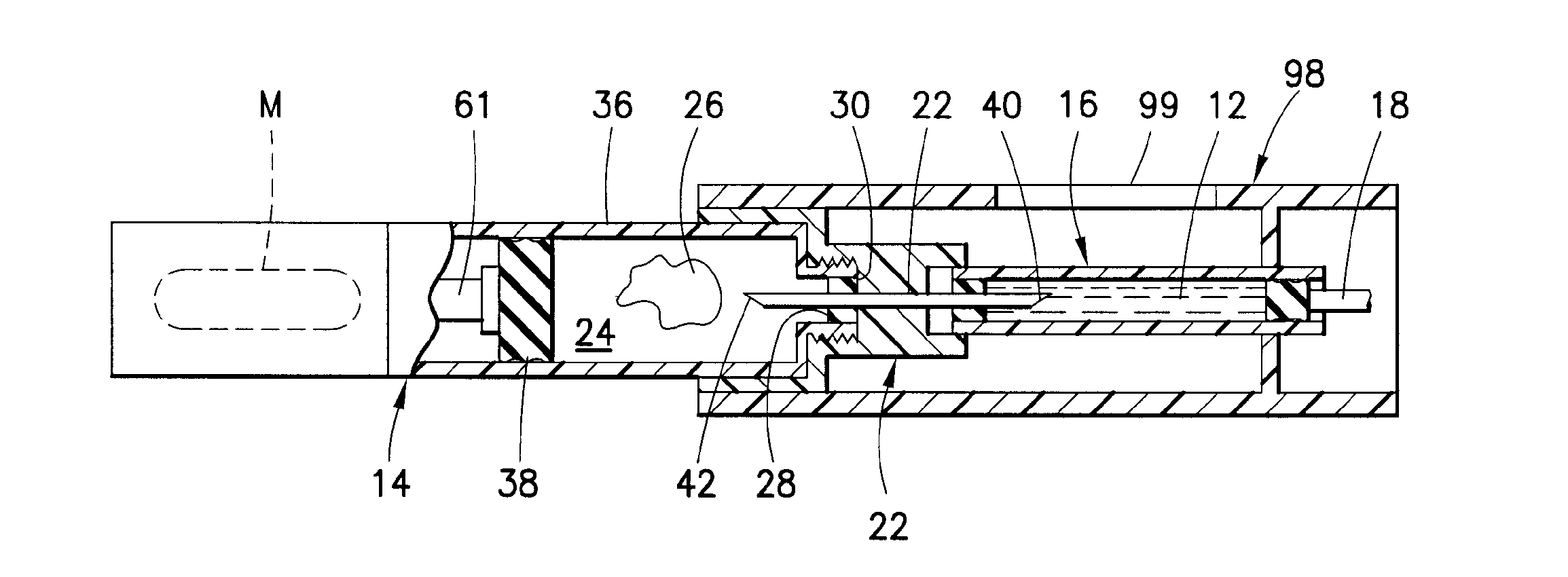
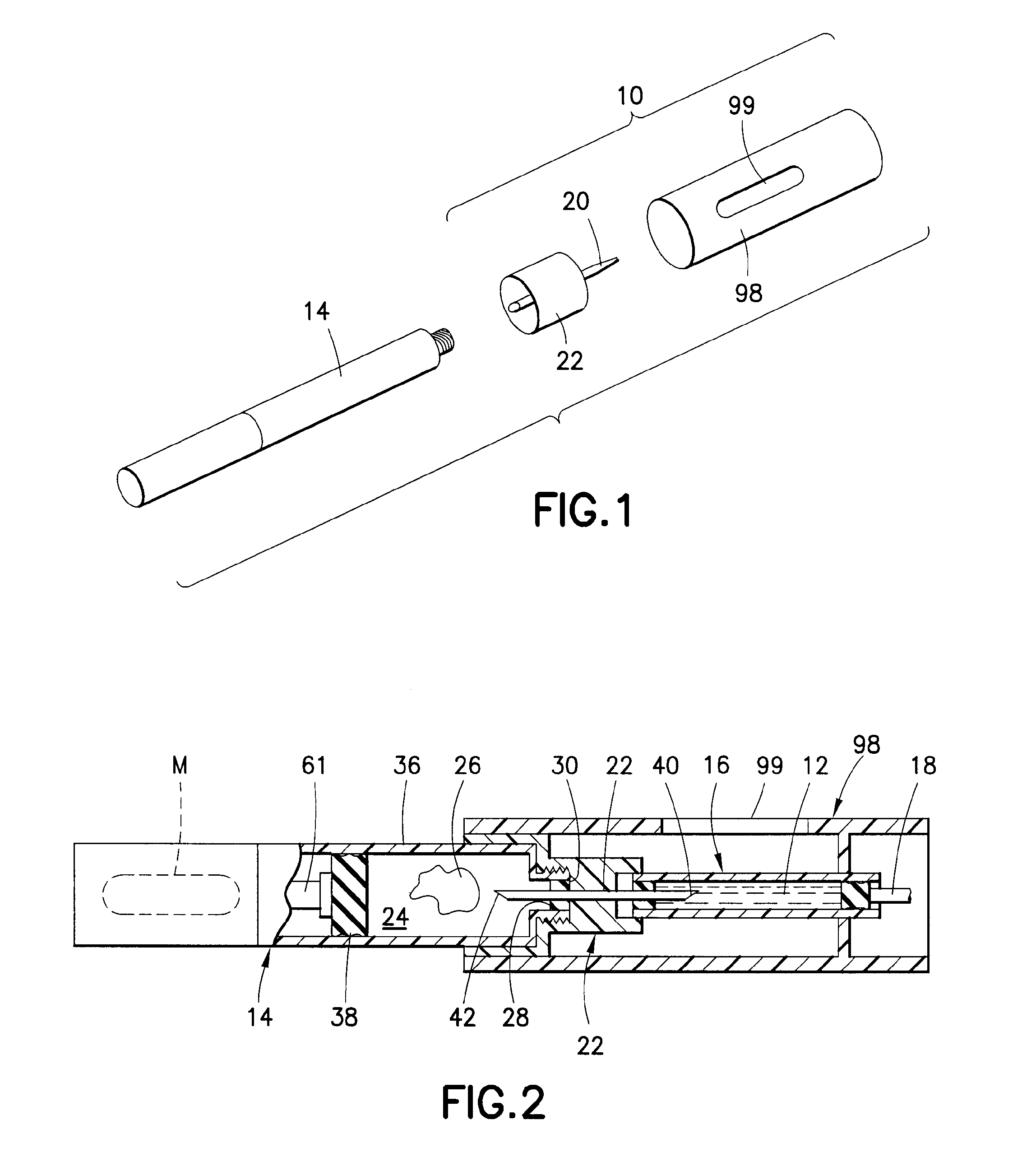
[0023]With reference to the Figures, a mixing device 10 is shown suitable for introducing flowable material 12 into a pen injector 14. The mixing device 10 generally includes a reservoir 16 formed to accommodate the flowable material 12; a displaceable plunger 18 for urging the flowable material 12 from the reservoir 16; a cannula 20; and, a fixturing member 22. The flowable material 12 may be introduced into a reservoir 24 in the pen injector 14 so as to be mixed with a secondary material 26 located therein. In this manner, substances may be mixed inside of the pen injector 14 in forming a mixed solution suitable for injection by the pen injector 14.

[0024]As used herein, the term “distal” and derivatives thereof, refer to a direction from the mixing device 10 and towards the pen injector 14, while the term “proximal”, and derivatives thereof, refer to a direction away from the pen injector 14 and towards the mixing device 10.

[0025]The flowable material 12 may be in any flowable for...


PUM

PropertyMeasurementUnit
Forceaaaaaaaaaa
Flow rateaaaaaaaaaa
Mixtureaaaaaaaaaa

Abstract

In one aspect, a fixturing member for fixing a source of flowable material relative to a pen injector so as to permit introduction of the flowable material into the pen injector is provided herein. The fixturing member includes a body having a web with opposing proximal and distal faces. A distal wall extends distally from the distal face of the web, with the distal wall at least partially encompassing a distal chamber. Features are formed on the body for removable mounting onto a pen injector. Also, features are formed on the body for mounting onto a source of flowable material, A cannula extends through the web the cannula having proximal and distal ends with a lumen extending therebetween. The distal end of the cannula is located in the distal chamber and positioned such that, with the member being mounted to a pen injector, the distal end is located to be in the pen injector. The proximal end of the cannula is located proximally of the proximally face of the web such that, with the member being mounted to a source of flowable material, the proximal end of the cannula is located to be in communication with the flowable material. Advantageously, with the subject invention, a fixturing member is provided which facilitates mixing of substances in a pen injector in preparing a pen injector for injection.

Description

FIELD OF THE INVENTION[0001]This invention relates to devices for mixing substances in preparation for injection by a pen injector.BACKGROUND OF THE INVENTION[0002]Certain drugs or medicaments (those terms being used interchangeably herein) are preferably provided in powder or dry form (such as a lyophilized form), and require reconstitution prior to administration. Lyophilized drugs, for example, typically are supplied in a freeze-dried form that needs to be mixed with a diluent to reconstitute the substance into a form that is suitable for injection. Medicaments may also be provided in other dry or powder form that require reconstitution.[0003]In addition, drugs may be provided as multipart systems which require mix ng prior to administration. For example, one or more liquid (e.g., flowable (slurry or liquid)) components, and / or dry (e.g., powdered or granular) components may be provided in a drug container or delivery device which require mixing prior to administration. The compo...

Claims


Application Information

Patent Timeline
IPC IPC(8): A61M5/31B65B3/04
CPCA61J1/062A61J1/2096A61J2001/2072A61J2001/2037A61J2001/2013
Inventor CRONENBERG, RICHARDVEDRINE, LIONEL
Owner BECTON DICKINSON & CO
Why Eureka
Try Eureka