
Method And System For Communicating Display Port and Single-Link DVI/HDMI Information For Dual-Mode Devices

a dual-mode device and display port technology, applied in the direction of cathode-ray tube indicators, instruments, electric digital data processing, etc., can solve the problem that ddc cannot be easily mapped to an optical interface, and achieve the effect of long transmission distance and easy mapped to

Active Publication Date: 2012-07-05
ICRON TECH
View PDF5 Cites 20 Cited by
  • Summary
  • Abstract
  • Description
  • Claims
  • Application Information

AI Technical Summary

Benefits of technology

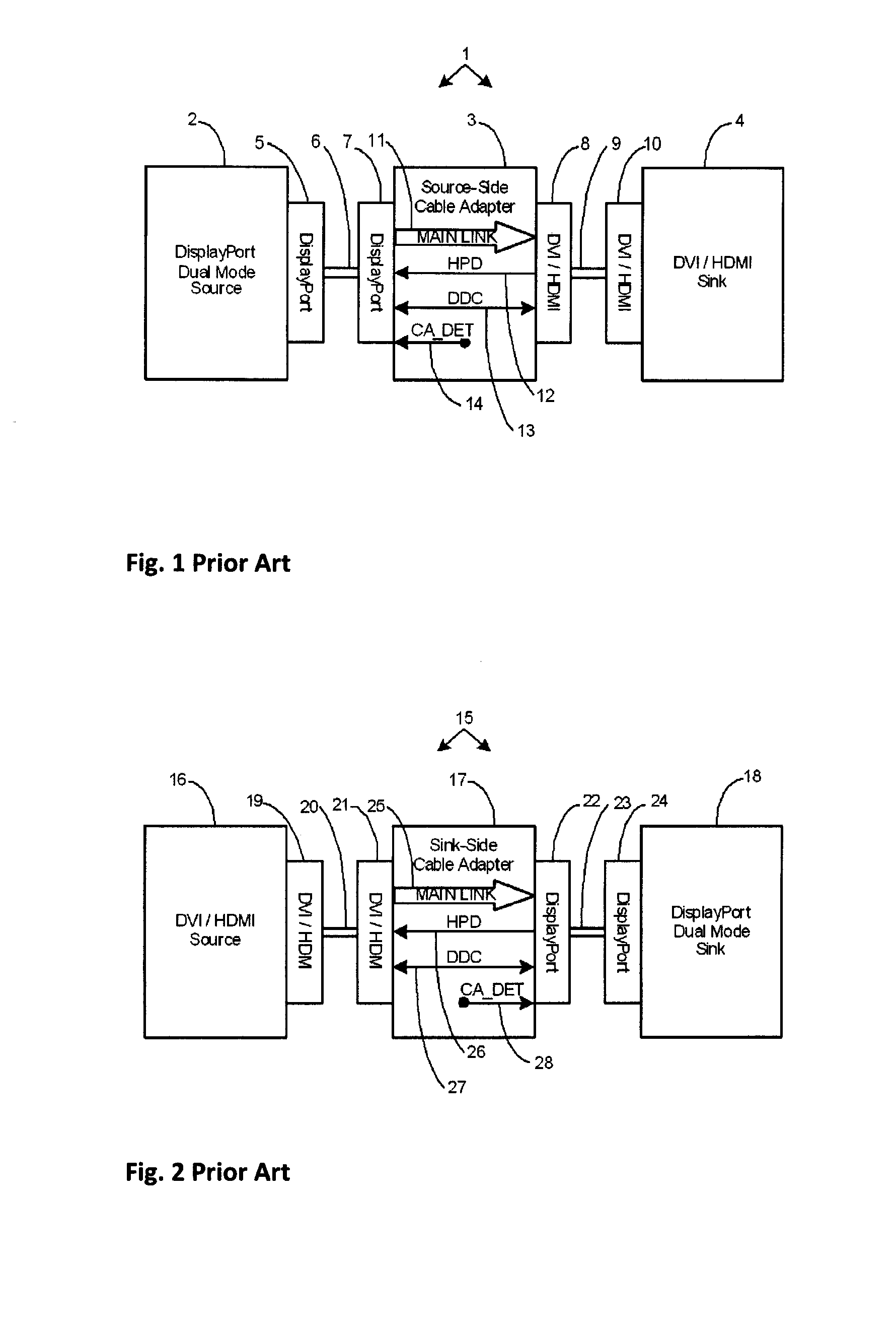
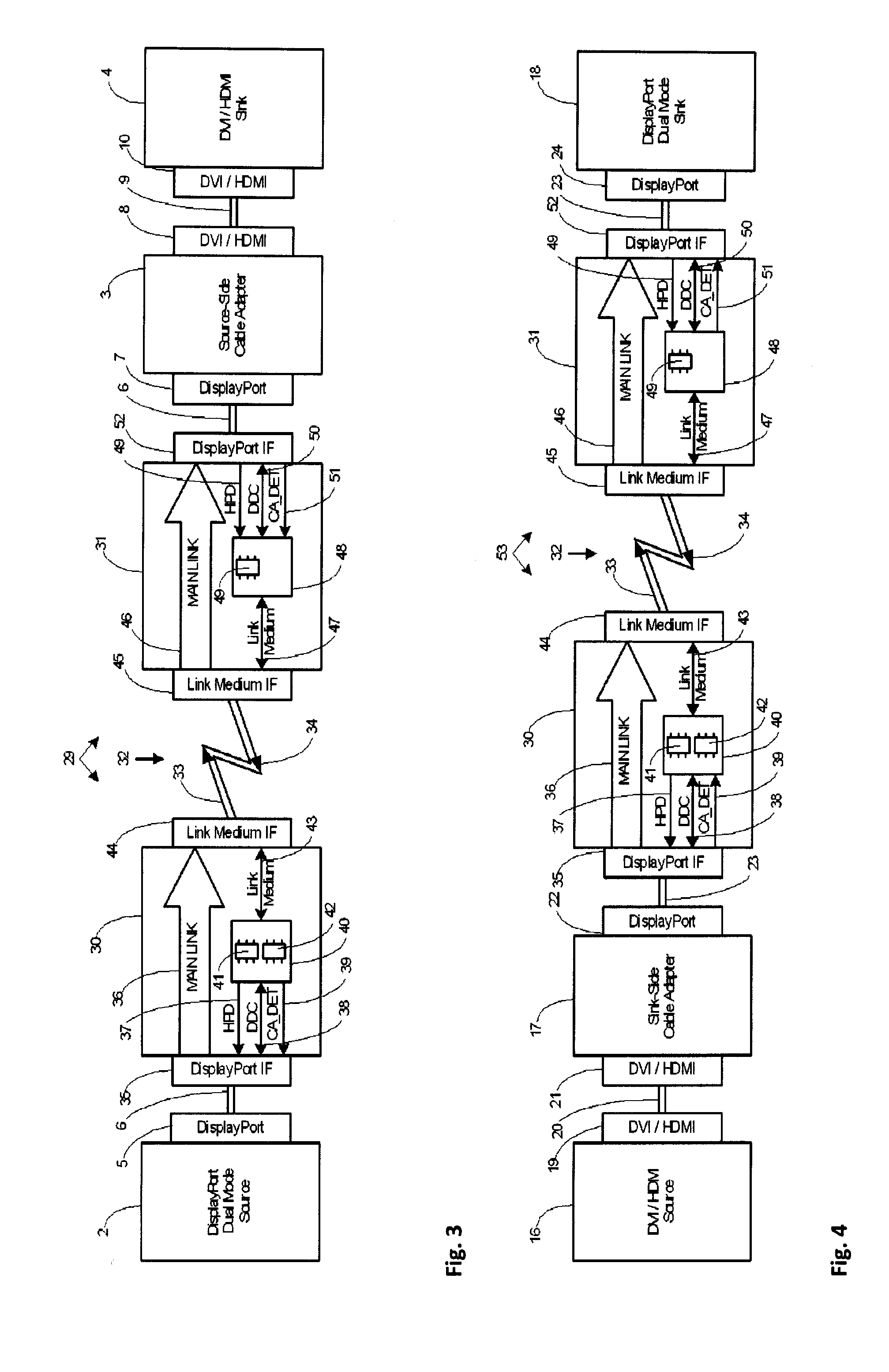
[0011]An advantage of the present invention's ability to allow connectivity to any suitable link medium is realized when, for example, a purely optical link is desired for all, or a portion of the link between a Dual-mode device and a Dual-mode cable adapter, either for electrical isolation or the desire to support longer transmission distances. In this situation, all of the main link pairs can be easily mapped to laser diodes to optically transmit on the source side, and photodiodes to receive on the cable adapter or sink side. The DDC, however, cannot be easily mapped to an optical interface because it is a half-duplex protocol. If DDC could be converted to a full-duplex link protocol then the ability to maintain a completely optical link in the data transmission connection, could be accomplished. Another advantage of the present invention's ability to allow connectivity to any suitable link medium is realized when Dual-mode signals are embedded into another communications protocol, such as Ethernet.
[0012]According to the present invention, a system for communicating video information in a Dual-mode environment includes: (i) a local unit for producing an incoming request packet in response to DVI or HDMI information, received by the local unit of the system (from either a DVI or HDMI or Dual-mode source device), and transmitting the incoming request packet to a remote unit of the system via a first simplex channel of a dual simplex communications link; and (ii) a remote unit for producing an incoming response packet in response to a DVI or HDMI or Dual-mode sink unit and transmitting the response packet to the local unit via a second simplex channel of the dual simplex communications link, wherein a communication link is provided between the local unit and the remote unit.
[0013]The local unit may optionally comprise a device for storing responses from the remote unit, and may also include a method to select response information stored at the local unit or response information received from the remote unit. The local unit may optionally include foreign device local transmitting means for producing foreign device downstream data in response to foreign device information received by the local unit from a foreign device and transmitting the foreign downstream data to the remote unit via the first simplex channel.
[0014]The remote unit may include remote outputting methods for outputting by the remote unit a representative DVI or HDMI information. The remote unit may include foreign remote transmitting means for producing foreign upstream data in response to foreign destination information received by the remote unit from a foreign destination device and transmitting the foreign upstream data to the local unit via the second simplex channel.
[0015]It is an objective of the present invention to provide methods and systems to provide a method of communicating Dual-mode Device data so that it can be packetized and distributed over various link mediums and lengths.
[0016]It is a further object of the present invention that the methods and system should preferably accommodate any transmission delays which are introduced by various link mediums and lengths.

Problems solved by technology

The DDC, however, cannot be easily mapped to an optical interface because it is a half-duplex protocol.

Method used


Image

  • Method And System For Communicating Display Port and Single-Link DVI/HDMI Information For Dual-Mode Devices
  • Method And System For Communicating Display Port and Single-Link DVI/HDMI Information For Dual-Mode Devices
  • Method And System For Communicating Display Port and Single-Link DVI/HDMI Information For Dual-Mode Devices

Examples


Embodiment Construction

[0078]A preferred embodiment of the present invention is its application in a video display environment. As such, details of the invention will be described with particular reference to video communication systems. However, the skilled artisan will appreciate that the system of the present invention might also be used in non-video applications.

[0079]In one preferred embodiment of a video communication system of the present invention, the video source device can be any standard unit or device that supports the DisplayPort Dual-mode specifications, such as computer graphics cards or video adapters.

[0080]Preferably the unit or device shall support the most recent version of the DisplayPort Dual-mode specifications, but units or devices that support only early versions of the DisplayPort Dual-mode specifications are also permissible.

[0081]In a further preferred embodiment of a video communication system, the video sink device can be any standard unit or device that supports the DisplayP...


PUM


Abstract

A system and method for communicating DVI (digital visual interface) and HDMI (high-definition multimedia interface) information is provided. The system includes a local unit operable to produce a downstream request packet in reaction to received DVI or HDMI information from a video source device and to transmit the request packet to a remote unit via a first simplex channel of a communications link. The remote unit operates to produce an upstream reply packet in reaction to received DVI or HDMI information by the remote unit from a video sink device and to transmit the reply packet to the local unit via a communications link. The system allows greater distances and allows various communications mediums to be used between the source and sink, and can communicate DVI and HDMI information and other information via a variety of different communications links.

Description

FIELD OF THE INVENTION[0001]This invention relates to methods and system for communicating the DVI (digital visual interface) and HDMI (high-definition multimedia interface) Display Data Channel, Hot Plug Detect and Cable Adapter Detect signals for, and between, Dual-mode Devices (DisplayPort and DVI and / or HDMI) over a variety of link mediums and communication protocols.DESCRIPTION OF THE PRIOR ART[0002]The VESA (Video Electronics Standards Association) DisplayPort Standard defines a scalable digital display interface, with optional audio and content protection capabilities for broad applications within PC and consumer electronic (CE) devices. The DisplayPort interface is designed to support both internal chip-to-chip and external box-to-box digital display connections. Potential internal chip-to-chip applications include usage within a notebook PC for driving a panel from a graphics controller, or usage within a monitor or TV for driving the display component from a display contro...

Claims


Application Information

Patent Timeline
IPC IPC(8): G06F3/00
CPCG06F3/1454G09G5/006G09G2370/16G09G2370/12G09G2370/10
Inventor LOO, EDWARD KHIN WUI
Owner ICRON TECH
Learn More