Method of manufacturing LED light bar and manufacturing equipment thereof

a technology of led light bars and manufacturing equipment, which is applied in the direction of soldering equipment, lighting and heating equipment, auxiliaries welding devices, etc., can solve the problems of leds which are regularly arranged on the printed circuit board to float and drift, light bars that cannot meet customer's requirements, and influence the overall performance of light bars

Inactive Publication Date: 2012-07-12
HON HAI PRECISION IND CO LTD
View PDF7 Cites 20 Cited by
  • Summary
  • Abstract
  • Description
  • Claims
  • Application Information

AI Technical Summary

Problems solved by technology

However, in the reflowing process, the molten solder paste may cause the LEDs which are regularly arranged on the printed circuit board to float and drift.
Thus, relative positions between the LEDs and th...

Method used


Image

  • Method of manufacturing LED light bar and manufacturing equipment thereof
  • Method of manufacturing LED light bar and manufacturing equipment thereof
  • Method of manufacturing LED light bar and manufacturing equipment thereof

Examples


Embodiment Construction

[0012]Reference will now be made to the figures to describe various embodiments of the present method of manufacturing LED light bar and manufacturing equipment thereof in detail.

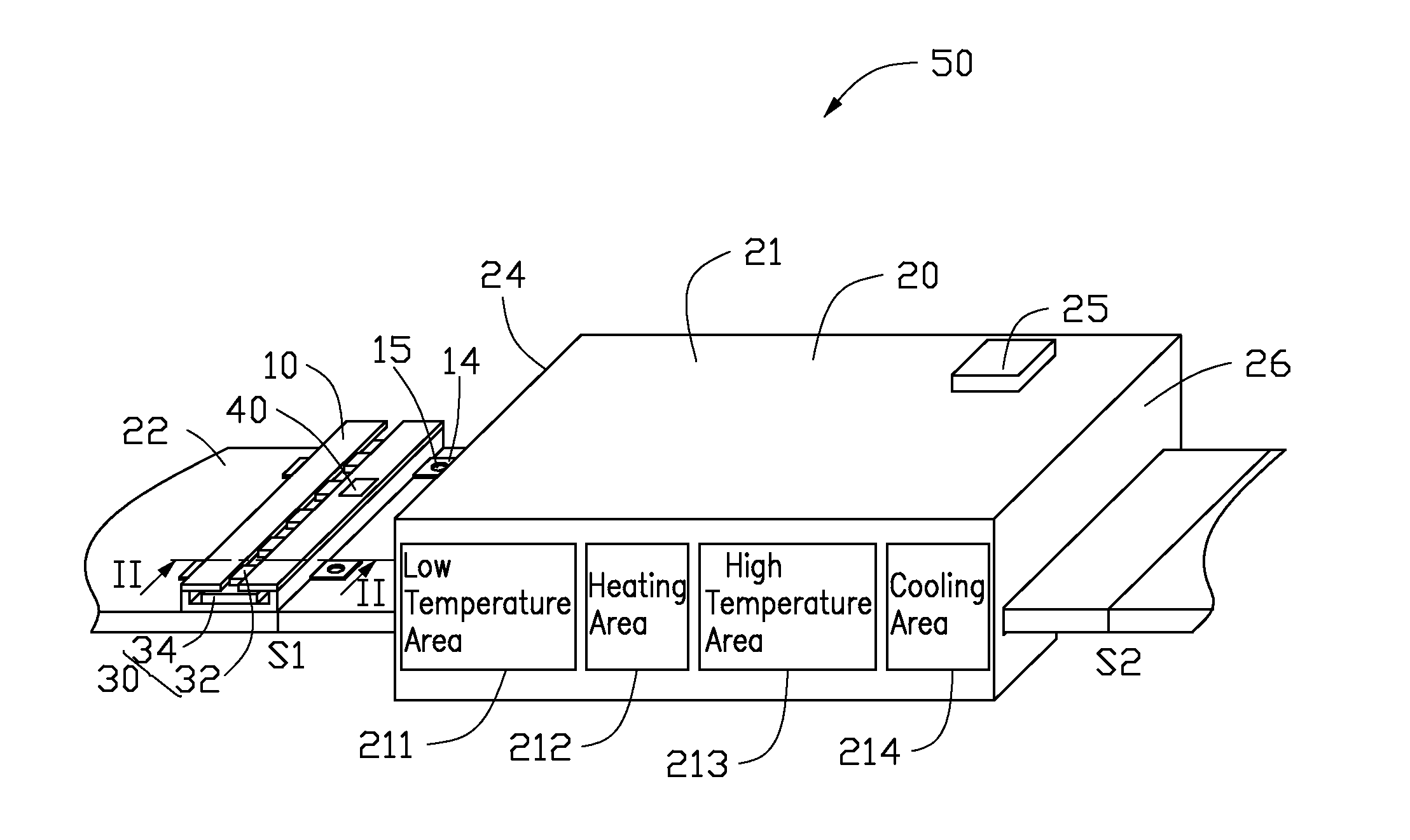
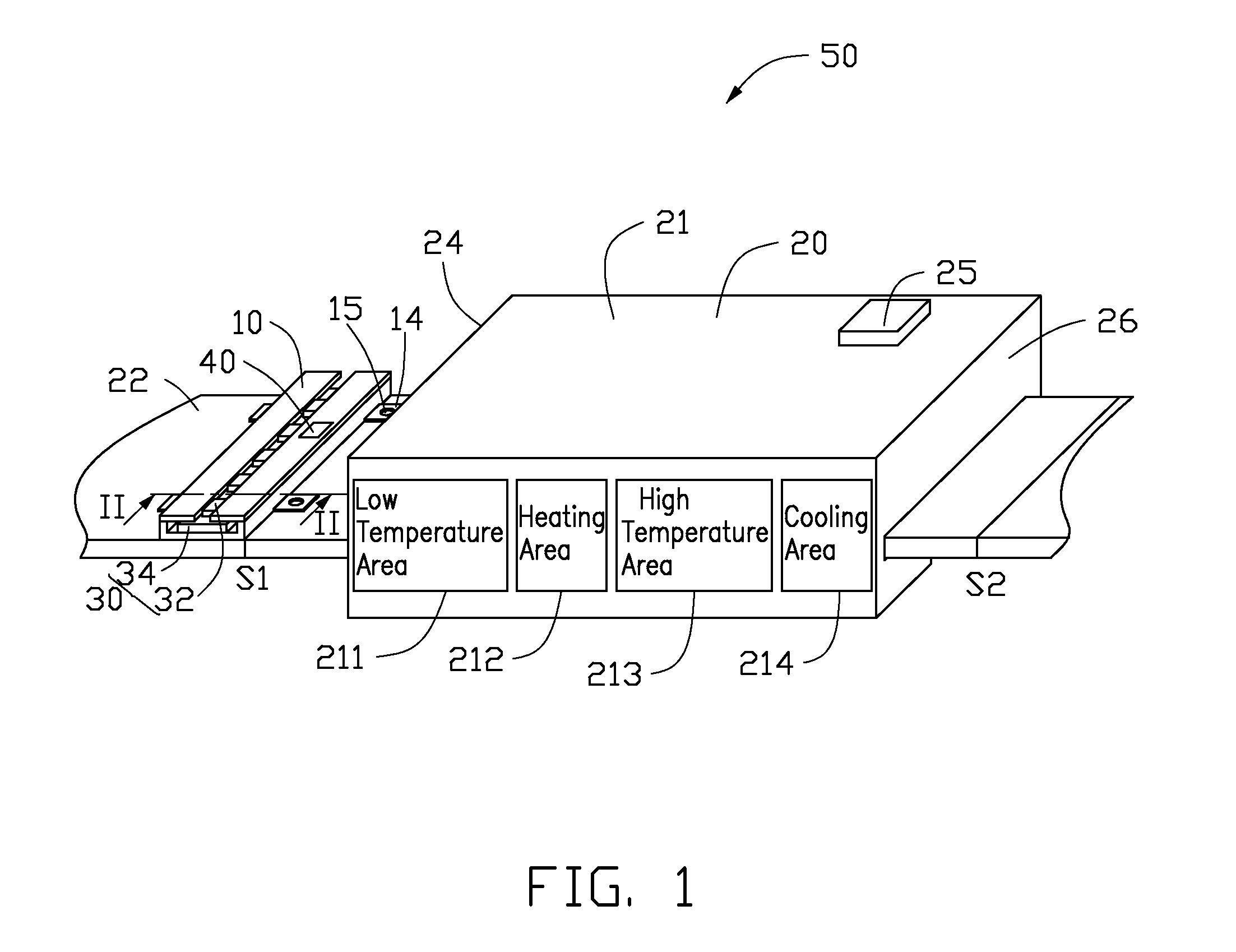
[0013]Referring to FIG. 1, a manufacturing equipment 50 for manufacturing an LED light bar 30 in accordance with an exemplary embodiment includes a reflow oven 20, a clamping device 10 and a position sensor 40. The LED light bar 30 includes a printed circuit board 34 and a plurality of LEDs 32 mounted on the printed circuit board 34 in a line.

[0014]The reflow oven 20 includes a hearth box 21, a transmitting belt 22 extended through the hearth box 21 and a control unit 25. The hearth box 21 defines an entrance 24 and an exit 26 at two opposite ends thereof. The hearth box 21 includes a low temperature area 211, a heating area 212, a high temperature area 213 and a cooling area 214 arranged in sequence in an interior of the hearth box 21 from the entrance 24 to the exit 26. Each of the low temperature area 21...


PUM

PropertyMeasurementUnit
Heightaaaaaaaaaa

Abstract

A manufacturing equipment for manufacturing an LED light bar includes a reflow oven and a clamping device. The LED light bar includes a printed circuit board and a plurality of LEDs arranged on the printed circuit board. The reflow oven includes a hearth box and a transmitting belt extended through the hearth box. The hearth box includes a heating area and a cooling area in an interior thereof. The clamping device is mounted on the transmitting belt. The clamping device defines a receiving space for receiving the LED light bar therein. The clamping device is changed between a clamping state for maintaining the LEDs in positions and a releasing state whereby the LED light bar can be removed from the clamping device.

Description

BACKGROUND[0001]1. Technical Field[0002]The disclosure relates to method of manufacturing semiconductor, and particularly to a method of manufacturing LED light bar and a manufacturing equipment thereof.[0003]2. Description of the Related Art[0004]Light emitting diodes (LEDs) have many advantages, such as high luminosity, low power consumption, compatibility with integrated circuits, easy driving, long term reliability, and environmental friendliness. These advantages have promoted wide use of the LEDs as a light source. Now, LEDs are commonly applied in lighting.[0005]A conventional LED light bar includes a printed circuit board and a plurality of LEDs mounted on the printed circuit board. When manufacturing the LED light bar, the LEDs are arranged on the printed circuit board in a line with a layer of solder paste applied therebetween; then, the printed circuit board with the LEDs thereon is conveyed through a reflow oven for a reflowing process, thereby enabling the solder paste ...

Claims


Application Information

Patent Timeline
IPC IPC(8): B23K31/02B23K3/00B23K3/08B23K1/00
CPCH01L24/80H01L2224/75272H01L2924/12041H01L2224/29101B23K1/00B23K3/00B23K3/08B23K31/02H01L24/00Y10S269/903F21K9/90H01L2224/83948H01L2224/75501Y10T29/53174H01L2224/75703H01L24/29H01L24/32H01L24/75H01L24/83H01L24/95H01L2224/32225H01L2224/75804H01L2224/83048H01L2224/83815H01L2224/7598H01L2924/014H01L2924/00014H01L2924/14H01L2924/00
Inventor LAI, CHIH-CHEN
Owner HON HAI PRECISION IND CO LTD
Why Eureka
Try Eureka