Wireless Power and Data Transfer Device for Harsh and Extreme Environments

a technology of data transmission device and wireless connection, which is applied in the direction of transformer/inductance circuit, transformer/inductance details, inductance, etc., can solve the problems of cost prohibitive, and achieve the effect of reducing the radiated magnetic nois

Active Publication Date: 2012-07-12
MONTEREY BAY AQUARIUM RES INST
View PDF1 Cites 69 Cited by
  • Summary
  • Abstract
  • Description
  • Claims
  • Application Information

AI Technical Summary

Benefits of technology

[0007]Maintenance of science instrumentation motivated the wireless power and data connector design described herein as a way to change out instrumentation without the need to recover the entire experiment platform. The wireless power and data connector reduces cost, provides galvanic isolation to avoid ground faults and improves reliability by eliminating corrosion of metallic contacts.
[0010]An array of sockets, analogous to a power strip, are packaged to share the same power input wire as a means to minimize associated cabling and connectors thus reducing overall system cost for the end user. The design provides support for a variety of data connections such as (and not limited to) point to point RS232 serial data, multi-drop connections such as RS485, CAN-bus, and Ethernet. Connectivity options such as USB, as well as wireless protocols brought in by wire such as Bluetooth and 802.11 are also scoped into the design.
[0011]Both the socket and plug are packaged in materials that suit the application environment. These materials have the following properties: 1) highly resistant to corrosive liquids, 2) able to withstand sustained high pressures of ‘full ocean depth’, 3) anti-static, and 4) wear resistant.
[0015]Planar coils, dissected toroid, and c-core are supported by the adaptable electronics and software. The choice of magnetic media is determined by the maximum power and size of the connector assembly. For planar coils, magnetic material is used as a backing to route the flux lines and minimize radiated magnetic noise.

Problems solved by technology

Accordingly, there is need for a ‘wet mate-able’ connector as the alternative is to pull up the entire system, which is cost prohibitive.

Method used


Image

  • Wireless Power and Data Transfer Device for Harsh and Extreme Environments
  • Wireless Power and Data Transfer Device for Harsh and Extreme Environments
  • Wireless Power and Data Transfer Device for Harsh and Extreme Environments

Examples


Embodiment Construction

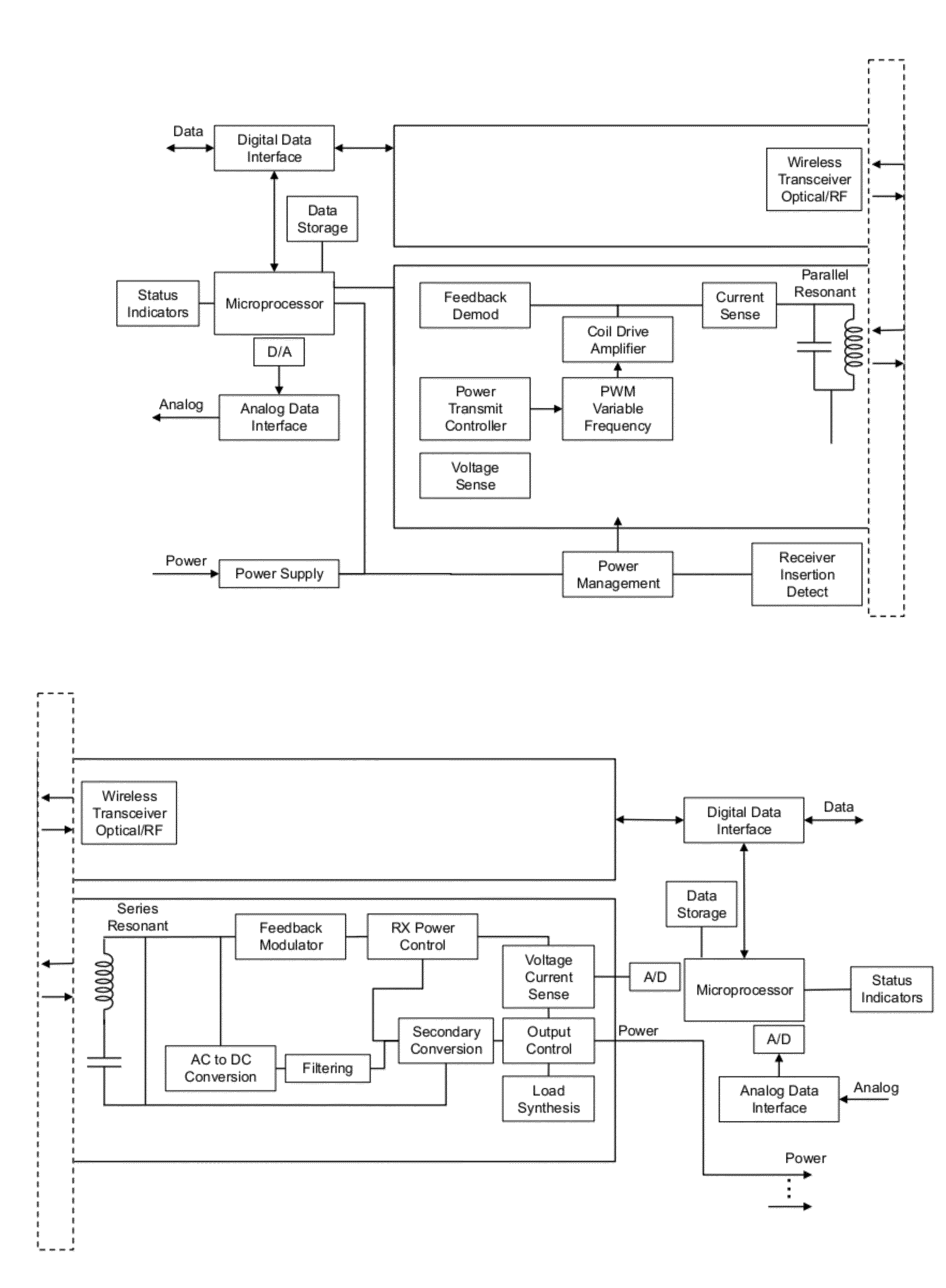
[0022]The following description of the details of preferred embodiments of the system are organized by mechanical, magnetic, electrical and software aspects.

[0023]Mechanical

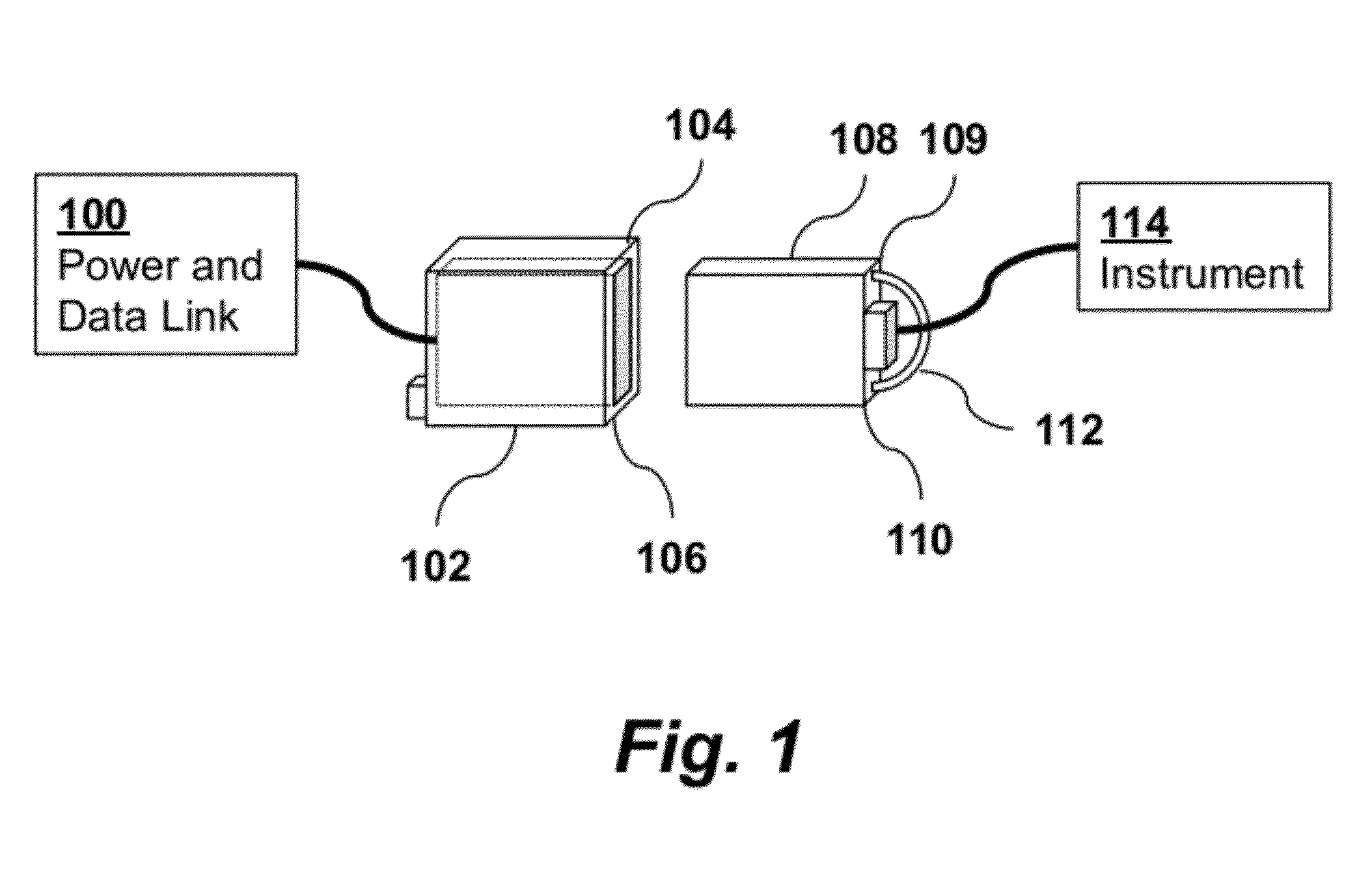
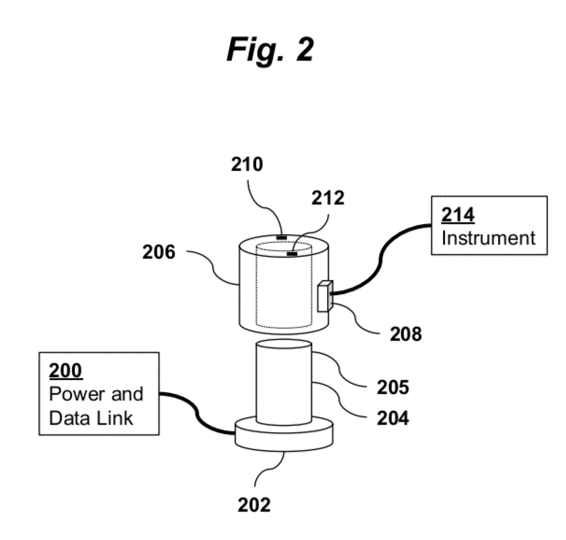
[0024]Various package options adaptable to magnetic and electronic circuit options and end applications are foreseen. The first designs to be reduced to practice are a paddle style plug and mating socket (FIG. 1) and a concentric cylinder plug and mating socket (FIG. 2). The paddle style design shown in FIG. 1 has a socket 102 connected to a power and data link 100, and a plug 108 connected to an instrument 114. Socket 102 has a power indicator 104 and data indicator 106. Similarly, plug 108 has a power indicator 109 and data indicator 110. The cylindrical style design shown in FIG. 2 has a socket composed of a puck element 202 containing electronics and a resonant transformer core 204 and data transfer section 205. A mating plug is composed of a puck element and electronics 208 and a data transfer section 206 ha...


PUM

PropertyMeasurementUnit
depthaaaaaaaaaa
depthaaaaaaaaaa
poweraaaaaaaaaa

Abstract

A wireless power and data connector includes a socket and a plug. The socket has a power port for connecting to a wired power transmission line, a data port for connecting to a wired data communication line, a wireless power transmitter, and a wireless data transceiver. The plug includes a power port for connecting to a wired instrument power transmission line, a data port for connecting to a wired instrument data communication line, a wireless power receiver, and a wireless data transceiver. The socket has a concave portion and the plug has a convex region shaped such that the convex region of the plug removably fits within the concave region of the socket. The wireless power transmitter and wireless power receiver transmit power from the socket to the plug using magnetically coupled resonant tank circuits.

Description

CROSS-REFERENCE TO RELATED APPLICATIONS[0001]This application is a continuation of U.S. patent application Ser. No. 13 / 232674 filed Sep. 14, 2011, which claims priority from U.S. Provisional Patent Application No. 61 / 403335 filed Sep. 14, 2010, both of which are incorporated herein by reference.FIELD OF THE INVENTION[0002]The present invention relates generally to wireless data and power transmission connector technology. More specifically, the invention relates to wireless transfer for data and power transmission in harsh environments such as under water.BACKGROUND OF THE INVENTION[0003]The need for an inexpensive and reliable method of sub-sea connection is well established. That need is growing with the advent of continuous ocean presence programs such as the Ocean Observing Initiative (OOI) and similar projects around the world. Maintenance operations typically involve removal and replacement of scientific instruments and sensors. Accordingly, there is need for a ‘wet mate-able’...

Claims


Application Information

Patent Timeline
Patent Type & Authority Applications(United States)
IPC IPC(8): H01F38/00
CPCH01F38/14
Inventor MAUGHAN, THOMAS G.KIRKWOOD, WILLIAM J.
Owner MONTEREY BAY AQUARIUM RES INST
Why Eureka
Try Eureka