Energy storage system and controlling method thereof

Active Publication Date: 2012-07-12
HANWHA SOLUTIONS CORP
View PDF7 Cites 52 Cited by
  • Summary
  • Abstract
  • Description
  • Claims
  • Application Information

AI Technical Summary

Benefits of technology

[0007]According to one or more embodiments of the present invention, frequent operation mode changes of

Problems solved by technology

As environmental destruction, resource depletion, etc., become serious problems, interest in

Method used


Image

  • Energy storage system and controlling method thereof
  • Energy storage system and controlling method thereof
  • Energy storage system and controlling method thereof

Examples


first embodiment

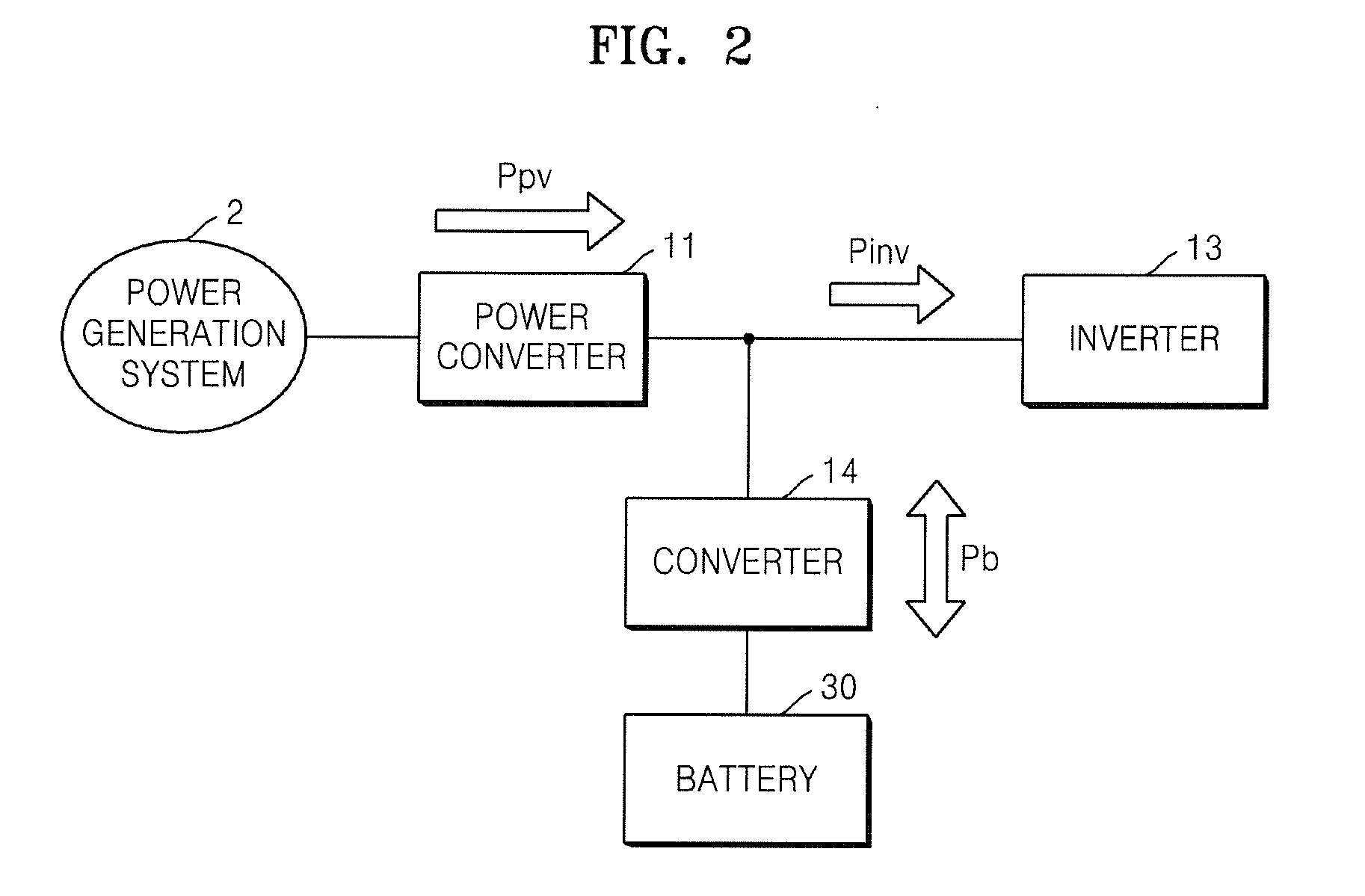
[0070]FIGS. 3 and 4 are graphs illustrating the operation mode of FIG. 2, according to an embodiment of the present invention. A determination of the operation mode of the converter 14 is set as follows.

[0071]

[0072]An operation of the converter 14 stops (changes to an off state) for a preset time after an operation mode change threshold point of the converter 14 occurs.

[0073]Referring to FIG. 3, an upper graph illustrates an amount of power generated by the power generation system 2, and a lower graph illustrates an amount of power supplied into or supplied from the battery 30. A preset amount of power output from the inverter 13, i.e., rated power of the inverter 13, is set to Pr.

[0074]Ppv is higher than Pr before a first time t1, and this indicates that the power generation system 2 generates an amount of power larger than an amount of power demanded by the inverter 13. Therefore, power corresponding to a part of Ppv exceeding Pr is used to charge the battery 30.

[0075]Since Ppv fa...

second embodiment

[0092]FIGS. 11 and 12 are graphs illustrating the operation mode of the converter 14 shown in FIG. 2, according to another embodiment of the present invention. A determination of the operation mode of the converter 14 is set as follows.

[0093]

[0094]An off state section of the converter 14 is set.

[0095]Referring to FIG. 11, an upper graph illustrates an amount of power generated by the power generation system 2, and a lower graph illustrates an amount of power supplied into or supplied from the battery 30. A preset amount of power output from the inverter 13, i.e., rated power of the inverter 13, is set to Pro. An upper limit of an off state section in which the converter 14 is switched off is set to Pra, and a lower limit of the off state section is set to Prb. Ppv is higher than Pra before a first time t1, and this indicates that the power generation system 2 generates an amount of power larger than an amount of power demanded by the inverter 13. Therefore, excess power not supplied...

third embodiment

[0100]FIGS. 13 and 14 are graphs illustrating the operation mode of the converter 14 shown in FIG. 2, according to another embodiment of the present invention. A determination of the operation mode of the converter 14 is set as follows.

[0101]

[0102]An off state section of the converter 14 is set.

[0103]A hysteresis section of the off state section is set.

[0104]Referring to FIG. 13, an upper graph illustrates an amount of power generated by the power generation system 2, and a lower graph illustrates an amount of power supplied into or supplied from the battery 30. As in the embodiment of FIG. 11, in the present embodiment, rated power of the inverter 13 is set to Pro, an upper limit of an off state section is set to Pra, and a lower limit of the off state section is set to Prb. Also, in the present embodiment, a hysteresis section is set to Ph1, Ph2, Ph3, and Ph4 with respect to Pra and Prb. The hysteresis section prevents an operation mode change of the converter 14 from frequently o...


PUM


Abstract

An energy storage system and a controlling method thereof are provided. Accordingly, an operation mode of the energy storage system is stably changed. The energy storage system includes: a battery; an inverter for receiving a first power from an external source and generating a second power; and a converter coupled between the battery and both the external source and the inverter. The converter is configured to enter an off mode between a charge mode for charging the battery and a discharge mode for discharging the battery.

Description

CROSS-REFERENCE TO RELATED APPLICATION[0001]This application claims priority to and the benefit of U.S. Provisional Patent Application No. 61 / 432,127, filed on Jan. 12, 2011, the entire content of which is incorporated herein by reference.BACKGROUND[0002]1. Field[0003]Aspects of one or more embodiments according to the present invention relate to an energy storage system and a controlling method thereof.[0004]2. Description of Related Art[0005]As environmental destruction, resource depletion, etc., become serious problems, interest in a system capable of storing energy and efficiently using the stored energy has been increased. In addition, interest in renewable energy, which does not generate pollution or generates little pollution in a development process, has been increased. An energy storage system that interconnects an existing grid, a renewable energy source, and a battery system that stores power has been researched and developed to cope with today's environmental changes. Th...

Claims


Application Information

Patent Timeline
IPC IPC(8): H02J7/00
CPCH02J3/32H02J3/383H02J3/386H02J7/34H02J9/062Y02B10/72Y02E10/566Y02E10/763H02J3/385H02J3/382Y02E10/58Y02E10/563Y02P90/50H02J2300/28H02J2300/20H02J2300/26H02J2300/24H02J3/381Y02E10/56Y02E10/76Y02P80/10Y02B10/70Y02E60/10
Inventor LEE, SUNG-IM
Owner HANWHA SOLUTIONS CORP
Why Eureka
Try Eureka