Category 6a surge protector

a surge protector and surge protection technology, applied in the direction of overvoltage circuit protection, circuit electrostatic discharge protection, overvoltage circuit protection, etc., can solve the problems of known surge protector circuits suffering, certain known surge protector circuits have limitations on working bandwidth, and modern telecommunications related equipment is susceptible to transient surges, etc., to achieve low capacitance/low crosstalk, low return loss, and low attenuation

Inactive Publication Date: 2012-07-12
ILLINOIS TOOL WORKS INC
View PDF2 Cites 5 Cited by
  • Summary
  • Abstract
  • Description
  • Claims
  • Application Information

AI Technical Summary

Benefits of technology

[0012]Another advantage of the present invention is to provide a surge protector for protecting copper wire networks from over-voltage transients having a design that provides for low capacitance / low crosstalk as well as low attenuation and low return loss.
[0013]A further advantage of the present disclosure is to provide a surge protector for protecting copper wire networks from over-voltage transients, where the surge protector includes a printed circuit board having a unique trace layout for mounting the electrical circuit components of the surge protector and for passing data signals with minimal degradation.
[0014]In a preferred embodiment of the present invention, there is provided a surge protector for protecting telecommunications related equipment and other associated sensitive electrical components from over-voltage transient occurring on tip / ring conductors of telecommunication lines coupled thereto which includes a printed circuit board and surge protection circuits being mounted on the printed circuit board. The surge protection circuits are interconnected between incoming tip and ring terminals defining an unprotected side and outgoing tip and ring terminals defining a protected side.
[0015]The printed circuit board includes first through fourth pairs of tip and ring conductive traces. Each of the surge protection circuits has a first set of steering diodes, a pair of series-connected voltage clamping devices, and a second set of steering diodes. Each of the first set of steering diodes are interconnected between a respective tip conductive trace in the first through fourth pairs of tip and ring conductive traces and a first end of the pair of series-connected voltage clamping devices. Each of the second set of steering diodes are interconnected between a respective ring conductive trace in the first through fourth pairs of tip and ring conductive traces and a second end of the pair of series-connected voltage clamping devices.
[0016]Input side connector devices are coupled to the respective incoming tip and ring terminals for connecting to incoming telecommunication lines. Output side connector devices are coupled to the respective outgoing tip and ring terminals for connecting to customers' electrical equipment to be protected.
[0017]These and other advantages of the present disclosure will become more fully apparent from the following detailed disclosure, taken in conjunction with the accompanying sheets of drawings, wherein like numerals refer to like parts, elements, components, steps and processes, wherein:

Problems solved by technology

As is generally well known to those skilled in the telecommunications industry, modern telecommunications related equipment is susceptible to transient surges such as those caused by lightning strikes and other voltage / current surges occurring on the incoming power lines.
However, these known surge protector circuits suffer from a number of disadvantages.
For example, certain known surge protector circuits have a limitation on the working bandwidth, which is generally in the range of 250 MHz.

Method used


Image

  • Category 6a surge protector
  • Category 6a surge protector
  • Category 6a surge protector

Examples


Embodiment Construction

[0023]It is to be distinctly understood at the outset that the present invention shown in the drawings and described in detail in conjunction with the preferred embodiments is not intended to serve as a limitation upon the scope or teachings thereof, but is to be considered merely an exemplification of the principles of the present invention.

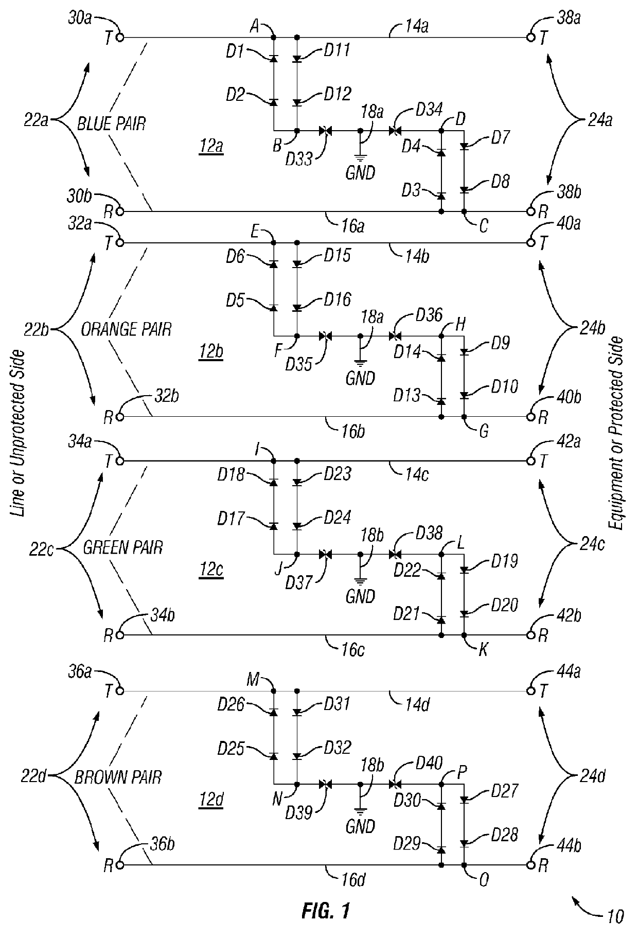
[0024]Referring now in detail to the various views of the drawings and in particular to FIGS. 1 through 4, there is illustrated a Category 6A surge protector 10 in accordance with the principles of the present invention. The Category 6A surge protector 10 has particular applications for use as a network interface for interconnection between incoming telecommunication lines carrying the voice / data signals in a signal distribution network and the different kinds of consumers' sensitive electrical equipment so as to protect the same from damage caused by transient voltage surges occurring on tip and / or conductors coupled to the telecommunication li...


PUM


Abstract

A surge protector for protecting telecommunications related equipment and other associated sensitive electrical components from over-voltage transient occurring on tip/ring conductors of communication lines coupled thereto includes a printed circuit board and surge protection circuits mounted on the printed circuit board. The surge protection circuits are interconnected between incoming tip and ring terminals defining an unprotected side and outgoing tip and ring terminals defining a protected side. Each of the surge protection circuits has a first set of steering diodes, a pair of series-connected voltage clamping devices, and a second set of steering diodes. Input side connector devices are coupled to the respective incoming tip and ring terminals for connecting to incoming telecommunication lines. Output side connector devices are coupled to the respective outgoing tip and ring terminals for connecting to customers' electrical equipment to be protected.

Description

CROSS-REFERENCE TO RELATED APPLICATION[0001]This application is a non-provisional application which claims the benefits of provisional application Ser. No. 61 / 430,364 filed on Jan. 6, 2011.BACKGROUND OF THE INVENTION[0002]1. Technical Field[0003]The present invention relates generally to surge protection devices for protecting telecommunications related equipment and associated sensitive electrical components from over-voltage transients.[0004]2. Prior Art[0005]As is generally well known to those skilled in the telecommunications industry, modern telecommunications related equipment is susceptible to transient surges such as those caused by lightning strikes and other voltage / current surges occurring on the incoming power lines. During the occurrence of the lightning strikes or the voltage / current surges on the incoming power lines in a power distribution network provided by electric utility companies, the power lines may become crossed-over or applied directly to the incoming telec...

Claims


Application Information

Patent Timeline
Patent Type & Authority Applications(United States)
IPC IPC(8): H02H3/20
CPCH04M3/18H05K1/0228H05K1/0257H05K2201/10174H05K2201/0746H05K2201/09236H05K2201/09727H05K1/0259
Inventor ADOMAITIS, MATTHEWURBAN, RICHARD J.
Owner ILLINOIS TOOL WORKS INC
Why Eureka
Try Eureka