

Object imaging system and x-ray diffraction imaging device for a security system
- Summary
- Abstract
- Description
- Claims
- Application Information
AI Technical Summary
Benefits of technology
Problems solved by technology
Method used
Image

Examples
Embodiment Construction
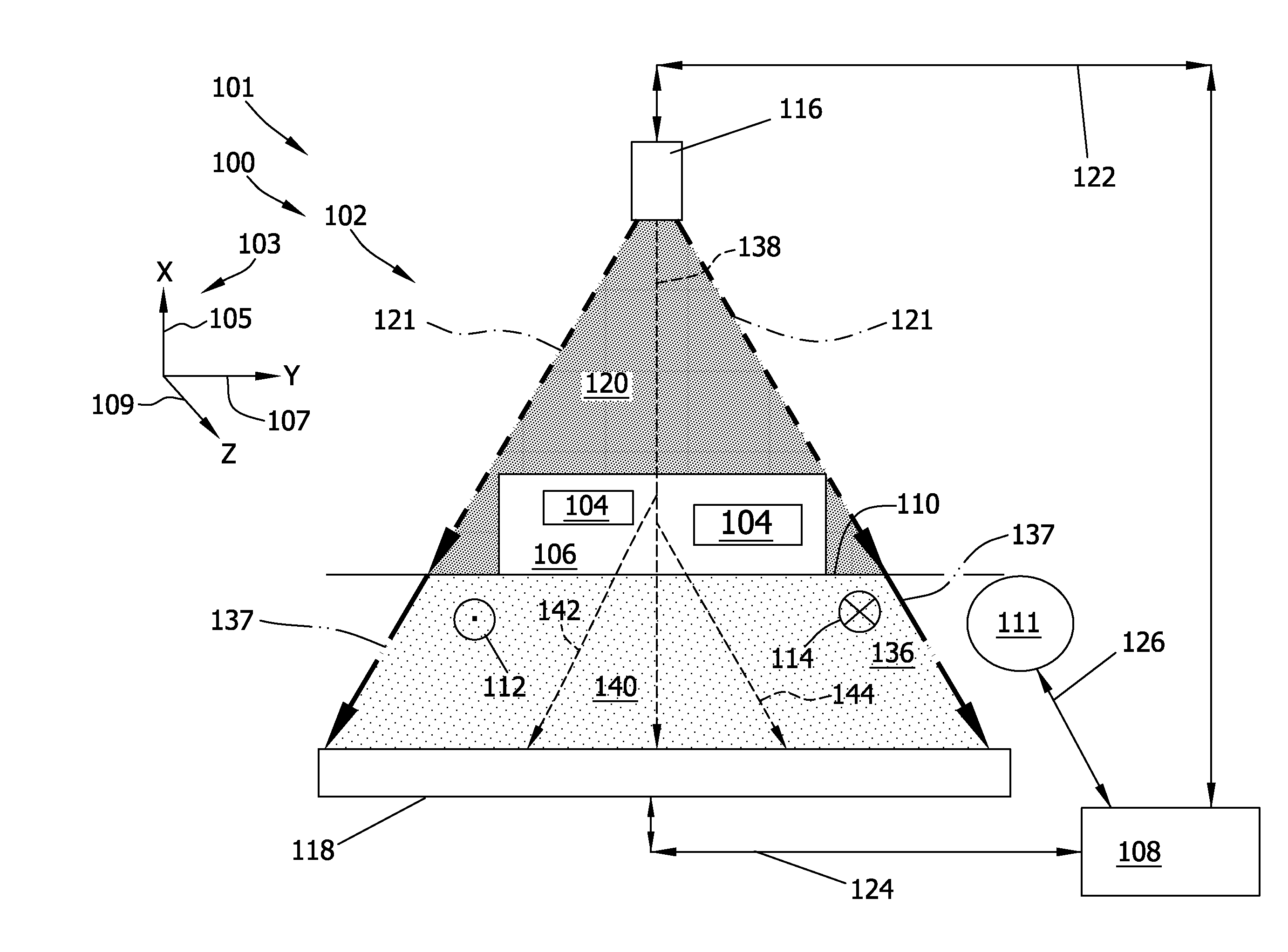
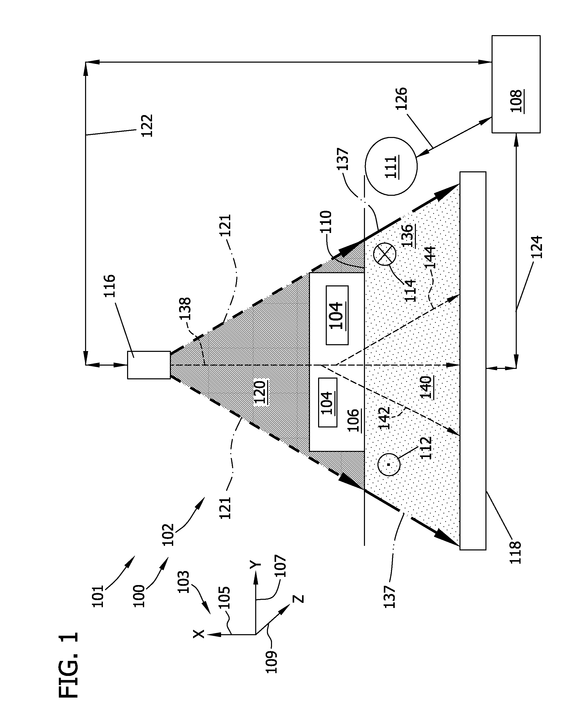
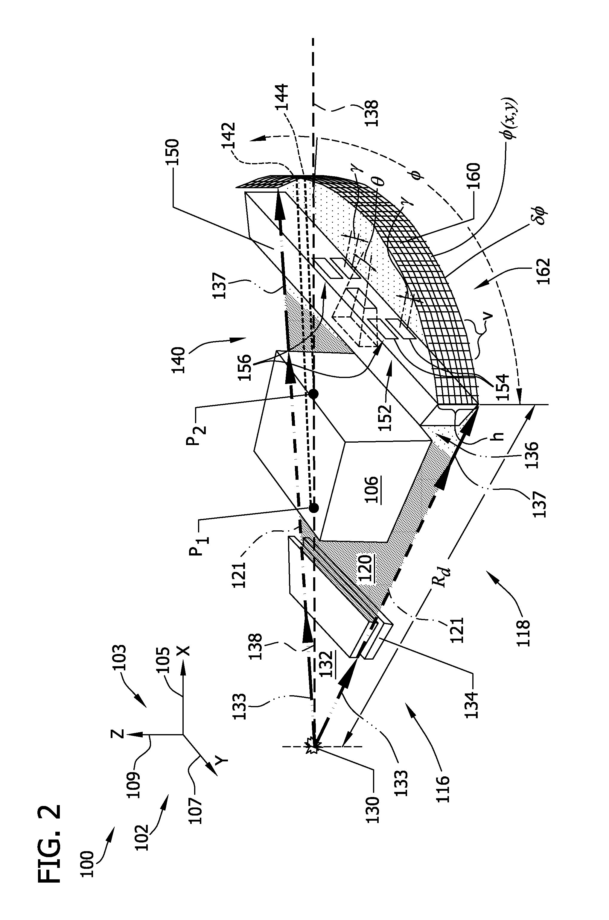
[0024]The method and fan-beam x-ray diffraction imaging (XDI) devices described herein facilitate effective and efficient operation of security systems. The security systems include an effective fan-beam XDI device that significantly decreases mechanical movements of the imaging device components and facilitates substantial parallel imaging and analysis of items under scrutiny. Such XDI device includes a multi-plane primary collimator that generates a plurality of x-ray fan-beams in which a plurality of detection volumes in a three-dimensional (3-D) object space are analyzed in parallel to generate a two-dimensional (2-D) image of an object and items residing therein. Such XDI device also includes a multi-plane secondary collimator that transmits a divergent scatter x-ray fan beam utilizing a large portion of the useful scattered x-rays while decreasing cross-talk x-rays. Therefore, such XDI device facilitates analyzing an energy-resolved spectra of the scattered x-rays with a 3-D r...
PUM
 Abstract
Description
Claims
Application Information