[0006]In the known pump housings, as already mentioned at the outset, numerous openings for valves and pump elements and the required connections, in particular for connection to the main cylinder, have to be provided. Some of these openings have to be connected hydraulically by connecting lines within the pump housing, while others have to be strictly separated. This gives rise to a necessary internal
line structure in the pump housing whose economical realization while allowing for the high requirements, especially as regards low weight, a small amount of space and, at the same time, extremely high
operational reliability, represents a difficult problem. As a part of known solutions to the problem, it is the customary practice in known pump housings for the connecting lines between the main cylinder openings and the associated pump element openings to be routed from a side face adjacent to the main cylinder openings, through the main cylinder openings, to the pump element openings. The reason for this is, in particular, that the pump element openings are situated in the central area of the pump housing and this known solution results in particularly short boring distances for the connecting lines. Short boring distances entail not only low production costs but obviously also require only a small amount of space.
[0008]Admittedly, the connecting line of this kind according to the invention thus requires more space within the pump housing but this is only a
disadvantage at first glance. Upon closer examination, it is namely found that such a configuration allows improved and space-saving routing of the lines within the pump housing overall and, as a result, it may even be possible to reduce the size of the pump housing in terms of its external dimensions. With the longer connecting line, more material is removed from within the pump housing, thereby even reducing the overall weight of the pump housing. This is another
advantage of the solution according to the invention.
[0009]Moreover, the invention has the
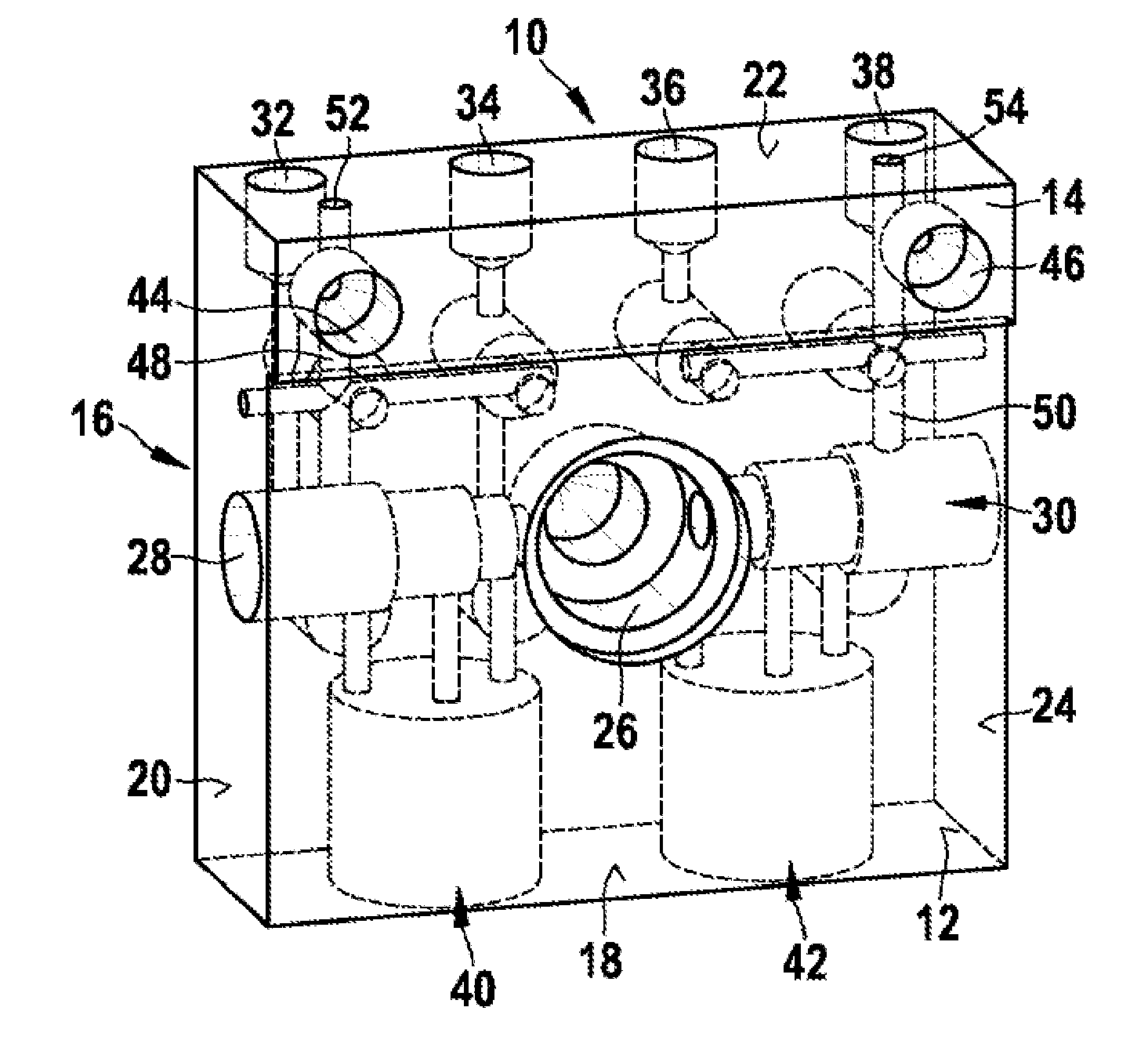
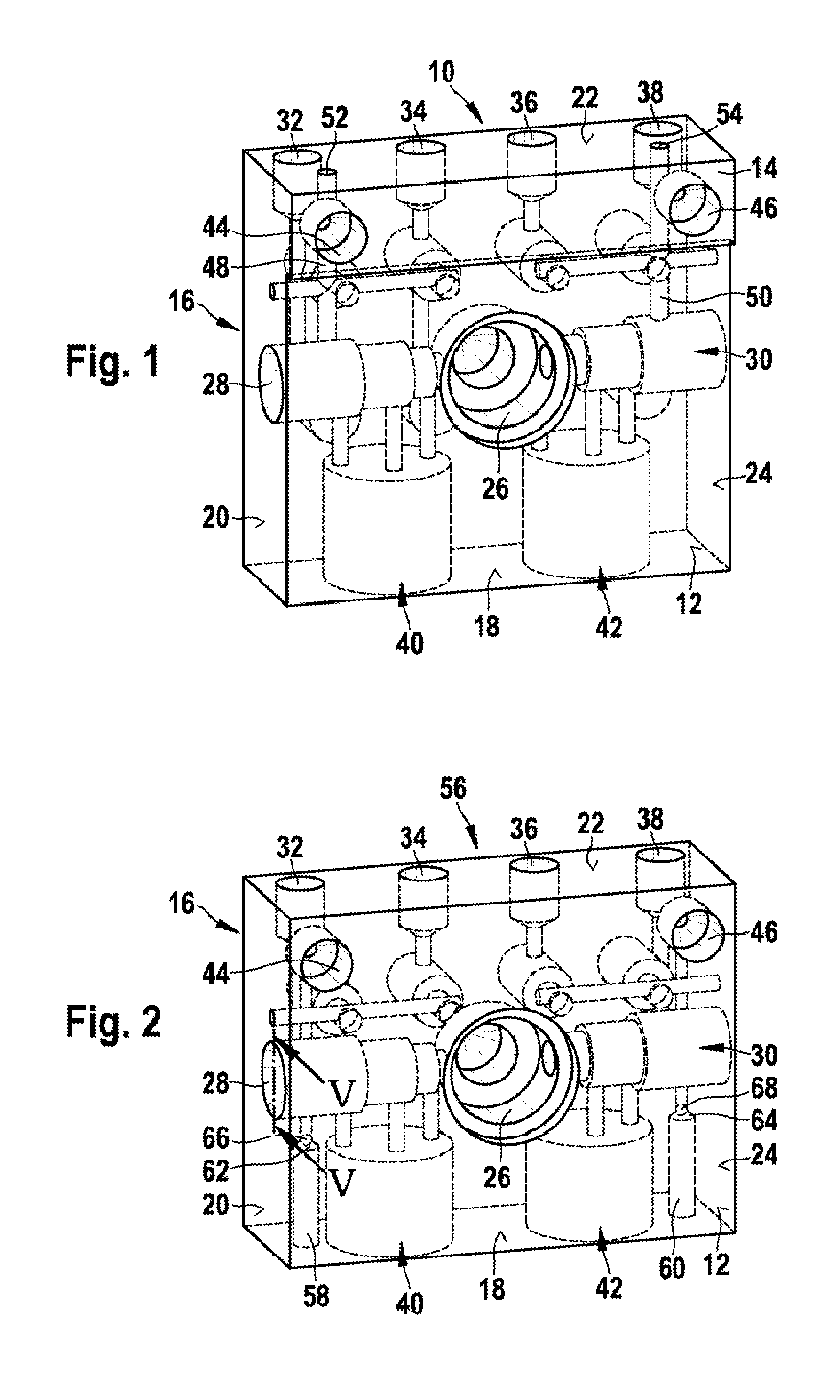
advantage that an “overhang”, which is required on known pump housings, can be eliminated. This overhang is a raised portion on one of the faces of the otherwise cuboidal pump housing, in which, in particular, two main cylinder connection openings are formed. These main cylinder connection openings must be arranged as far as possible away from an opening, formed centrally in the pump housing, for a drive eccentric and a motor pole housing in order to create enough space for
assembly. At the same time, the main cylinder connection openings must be at a sufficient distance from the other connection openings, in particular the
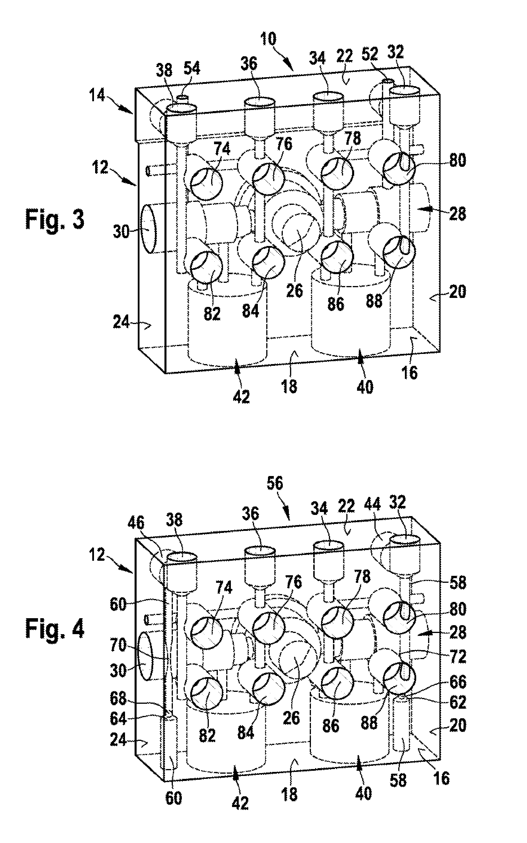
wheel cylinder connection openings and also the other line bores. Some of the line bores are provided with staked ball features, for which purpose a particularly large amount of material must be provided between the openings in order to avoid unwanted deformation of the material. In the case of known pump housings, this material which has to be provided has the effect that the main cylinder connection openings can no longer be arranged in the usual plane or surface of the cuboidal pump housing but “project” therefrom. As a result, the overhang mentioned is required as a second plane with an associated step. However, this entails additional costs in production and, in addition, difficulties in alignment for
assembly. During
assembly, the pump housing must be held in both planes, and these have dimensional tolerances relative to one another.
[0012]Said stepped bore and staked ball feature provide the basis for a small hydraulically used internal volume of the connecting line. The small internal volume is advantageous in respect of dead areas and a hydraulic damping effect, which should be avoided if at all possible.
[0014]The staked ball feature, which is thus formed on a bottom area of the accumulator bore or, in addition, in the
solid material of the pump housing, avoids an otherwise possible deformation of the pump housing and thus increases
operational reliability.
[0016]The
undercut is a low-cost way of creating the possibility of flow around the associated pump element, a possibility required for the operation of the motor vehicle hydraulic unit.

