Battery with a Stack of Bipolar Individual Battery Cells

Inactive Publication Date: 2012-07-12
DAIMLER AG
View PDF5 Cites 3 Cited by
  • Summary
  • Abstract
  • Description
  • Claims
  • Application Information

AI Technical Summary

Benefits of technology

[0007]Exemplary embodiments of the present invention are directed to a battery with a stack of individual battery cells, which avoids the disadvantages described above and which allows for a structure which can be implemented simply and cost-effectively.
[0010]In a particularly useful further development of the invention, the sheet metal covers and the electrode stack are joined by a pressure welding process. In this method, for example in ultrasonic welding or resistance pressure welding, the electrode geometry is to some extent impressed into the region of the welded components. In ultrasonic welding, for example, this may be a ribbed or knurled surface of the sonotrode and / or the anvil. These pressure welding methods, on the other hand, offer the advantage that different materials can be welded to one another. As, for example in the construction of the individual battery cell with a lithium ion cell chemistry, sheet metal covers made, for example, of iron-based materials have to be welded to aluminum foil anodes or copper foil cathodes, this advantage of pressure welding is critical in the production of such individual battery cells. The production of individual battery cells can therefore be simplified, which makes the production of the battery itself more cost-effective.

Problems solved by technology

This welding of the electrode foils or of their connecting regions to the respective sheet metal covers is disadvantageous because material is typically thrown up or raised in the region of the welds, which then prevents a flat contact between one individual battery cell and the sheet metal cover of the adjacent individual battery cell.
However, this is irrelevant here, because this structure is distanced from the opposite sheet metal cover by the electrolyte-filled region of the individual battery cell.
In order to obtain a flat contact of the sheet metal covers of adjacent individual battery cells even in the weld region, some reworking is required, which makes production complicated and expensive.
If the projecting regions of the welds were simply left on the sheet metal covers, the result would be an uncontrolled air gap at this point as well as a point contact between the sheet metal covers and the thrown-up material of the welds.
At the relatively high voltages in the stack of individual battery cells, this may even result in sparking in this region.

Method used


Image

  • Battery with a Stack of Bipolar Individual Battery Cells
  • Battery with a Stack of Bipolar Individual Battery Cells
  • Battery with a Stack of Bipolar Individual Battery Cells

Examples


Embodiment Construction

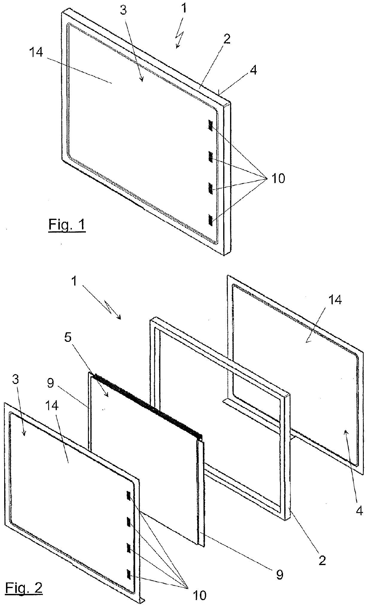
[0025]In FIG. 1, an individual battery cell 1 can be seen in a three-dimensional view. It comprises an electrically insulating frame 2, a first sheet metal cover 3 and a second sheet metal cover 4, which is located on the opposite side of the frame 2.

[0026]FIG. 2 is an exploded view of the same structure in which, in addition to the sheet metal covers 3, 4 and the frame 2, an electrode stack 5 can be seen. This electrode stack 5 is made up from anode foils 6 and cathode foils 7 with separators 8 placed in between. This structure is not recognizable in FIG. 2, but can be derived from the enlarged section of FIG. 7. The anode foils 6 and cathode foils 7 are stacked alternately, with an electrically insulating separator 8, typically also a foil material, placed between each anode foil 6 and cathode foil 7. On one side of the electrode stack 5, the anode foils 6 are led out therefrom, on the other side the cathode foils 7. These regions form the electric connecting regions 9, which can ...


PUM


Abstract

A battery includes a stack of bipolar individual battery cells, each of which includes an electrode stack and two sheet metal covers bounding the individual battery cell at least in the stacking direction. The electrode stack is connected to at least one of the sheet metal covers by at least one weld. In the region of the at least one weld, the sheet metal cover welded to the electrode stack and / or the sheet metal cover of the adjacent individual battery cell in contact with the sheet metal cover is / are of a set-back design. As a result, the sheet metal covers of adjacent individual battery cells do not have any contact in the region of the at least one weld.

Description

BACKGROUND AND SUMMARY OF THE INVENTION[0001]The invention relates to a battery with a stack of bipolar individual battery cells of the type defined in greater detail in the preamble of claim 1.[0002]Batteries represented by a stack of bipolar individual battery cells are generally known. The cells are stacked on top of one another and typically clamped together, so that one terminal post comes to lie on one side of the stack of bipolar individual battery cells, while the other terminal post lies on the other side of the stack of bipolar individual battery cells. Such individual battery cells are, for example, described in the German application number DE 10 2007 063 181.4. The individual battery cells are designed as so-called frame flat cells with two sheet metal covers, which are electrically isolated from each other by an insulating frame. The sheet metal covers serve as the terminals of the individual battery cell and as heat-conducting plates that divert the waste heat generat...

Claims


Application Information

Patent Timeline
IPC IPC(8): H01M10/02H01M10/0525H01M50/119
CPCH01M2/0212H01M2/027H01M2/0275H01M2/266H01M6/48H01M2/0285H01M10/0525H01M10/0585Y02E60/122H01M2/0426H01M2/0245H01M10/0436Y02P70/50Y02E60/10H01M50/545H01M50/119H01M50/169H01M50/258
Inventor SCHROETER, DIRKMEINTSCHEL, JENSERTLE, MARTINKAUFMANN, RAINERBRASSE, CLAUDIAHOHENTHANNER, CLAUS-RUPERTKAISER, JOERG
Owner DAIMLER AG
Why Eureka
Try Eureka