Onlay subcutaneous injection port

Inactive Publication Date: 2012-07-12
ROHRSCHEIB SIDNEY P
View PDF4 Cites 3 Cited by
  • Summary
  • Abstract
  • Description
  • Claims
  • Application Information

AI Technical Summary

Benefits of technology

[0004]This new design also reduces the possibility of puncturing the tubing during needle access to the port and reduces the possibility of port to become malpositioned or rotated due to the horizontal fixed tubing which eliminates all but one axis of freedom about which it can rotate. Additionally the onlay access port will be easier to place at surgery. Direct placement over a trochar site allow the tubing to be inserted through a smaller incision immediately below the only access port. This further enhances th

Problems solved by technology

This results in the most common complications in laparoscopic adjustable gastric banding which are the occlusion of tubing due to kinking and the loss of integrity of the tubing wall by cracking due to angulation stresses.
This new design also reduces

Method used


Image

  • Onlay subcutaneous injection port
  • Onlay subcutaneous injection port
  • Onlay subcutaneous injection port

Examples


Embodiment Construction

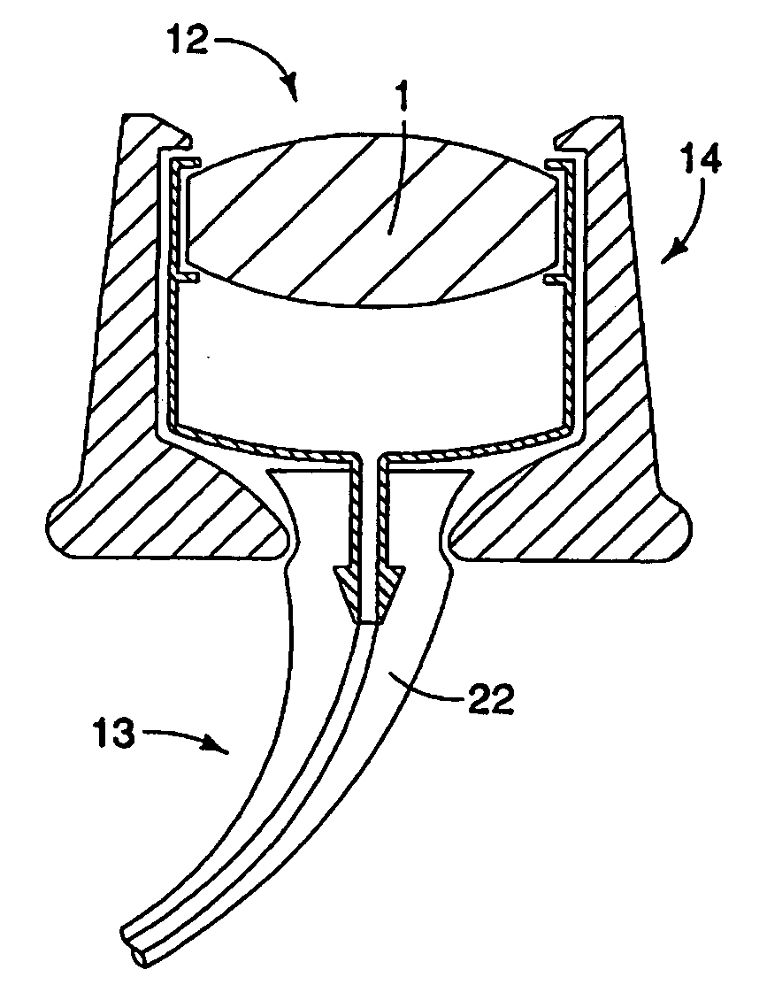
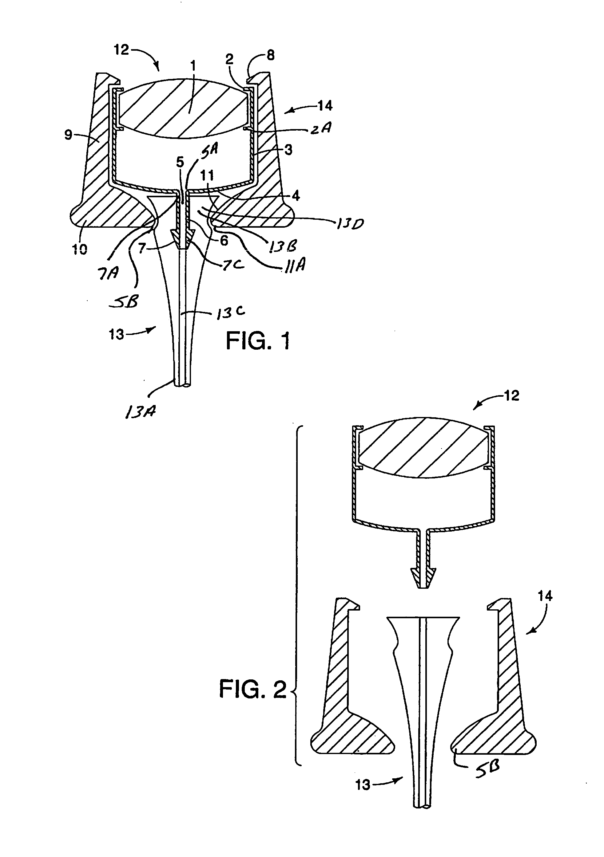
[0020]FIG. 1 shows the three major components of the access port, which are the injection chamber housing 14 with injection chamber 12 disposed within. Also partially disposed within the injection chamber housing is catheter 13. Catheter 13 exhibits a first catheter end 13A and a second catheter end 13B. Catheter 13 also exhibits a catheter fluid path 13C. Second catheter end 13B is disposed over catheter seat 6. Catheter seat 6 exhibits a first catheter seat end 7 and a second catheter seat end 7A. First catheter seat end 7 exhibits barbs 7C. Second catheter seat end 7A is attached to injection chamber bottom 4. Fluid path 5 extends through the center of catheter seat 6 and fluidly communicates with the injection chamber through first chamber aperture 5A in injection chamber bottom 4. Catheter 13 is disposed over catheter seat 6. The fluid path 5 of catheter seat 6 is fluidly communicates with the catheter fluid path 13C of catheter 13. Injection chamber housing 14 is annular in sh...


PUM


Abstract

The device is an implantable subcutaneous injection port used for various purposes including, but not limited to, vascular access and laparoscopic adjustable gastric banding. This device, with its tubing route and flexible connectors offers a solution to the problem of tubing occlusion and loss of integrity due to kinking. This device exhibits an injection chamber disposed within a housing. A self sealing septum is disposed within an injection chamber aperture. A second aperture communicates with a tube that is designed to connect to a catheter or other device suitable to the surgical application. Here the second aperture exits directly beneath the onlay port reducing the possibility of tubing kink, needle puncture and malpositioning seen with only ports where the catheter exits from the side of the device. An alternate embodiment utilizes a u-joint and ball joint to maximize the flexibility of the connection between the onlay port and the exiting catheter.

Description

CROSS REFERENCE TO RELATED APPLICATIONS[0001]This application is the National Stage of International Application No. PCT / US2009 / 000142, filed 9 Jan. 2009.TECHNICAL FIELD[0002]Implantable subcutaneous injection ports have been used primarily for the purpose of vascular access. The devices are generally implanted beneath the skin of a patient near the upper chest. The injection port exhibits a silicon membrane overlying a chamber which is, in turn, connected to tubing and catheter usually entering the internal jugular or subclavian vein. The chamber is accessed by puncturing the overlying skin with a Huber point needle, then puncturing the self sealing silicon membrane of the port. This allows the repeated injection of medicines or the drawing of blood with low risk of infection at the same time preserving the integrity of the skin. Various injection ports are commercially available. By way of example is the injection port available under the brand name of Port-A-Cath® Implantable Ven...

Claims


Application Information

Patent Timeline
IPC IPC(8): A61M5/00
CPCA61M2039/0229A61M39/0208
Inventor ROHRSCHEIB, SIDNEY P.
Owner ROHRSCHEIB SIDNEY P
Why Eureka
Try Eureka