Flow control diverter valve

a technology of flow control and diverter valve, which is applied in the direction of sealing/packing, instruments, and well accessories, etc., can solve the problems of running tools that cannot be retrieved, cannot extend back, and cannot be used to retrieve components

Inactive Publication Date: 2012-07-19
SCHLUMBERGER TECH CORP
View PDF7 Cites 38 Cited by
  • Summary
  • Abstract
  • Description
  • Claims
  • Application Information

AI Technical Summary

Benefits of technology

[0014]During drilling operations, cuttings are lifted to the surface by drilling fluid or mud flowing to the surface in the annular space between casing and liner. The flow directed into the annular space by the valve aids to prevent settling of the cuttings on the liner hanger control tool or running tool.
[0015]In another embodiment of the invention, a drop plug is dropped into the drill string and landed on the orifice ring. A circlip is located at a lower extension of the drop plug that passes through an inner diameter of the orifice ring. When sufficient pressure is applied to the drop plug, the shear screws attaching the orifice assembly to the sleeve are sheared, allowing the orifice ring and drop plug to move downstream. The circlip prevents the orifice ring and drop plug from becoming separated when moving downstream. Once the orifice ring is released, the orifice ring can be used to manipulate downstream tools by using the lower profile of the orifice ring as a drop ball.

Problems solved by technology

However, the liner does not extend back to the wellhead assembly at the surface.
This technique does not allow one to employ components that must be retrieved, which might include downhole steering tools, measuring while drilling instruments and retrievable drill bits.
The settled cuttings can cause the running tool to malfunction.

Method used


Image

  • Flow control diverter valve
  • Flow control diverter valve
  • Flow control diverter valve

Examples


Embodiment Construction

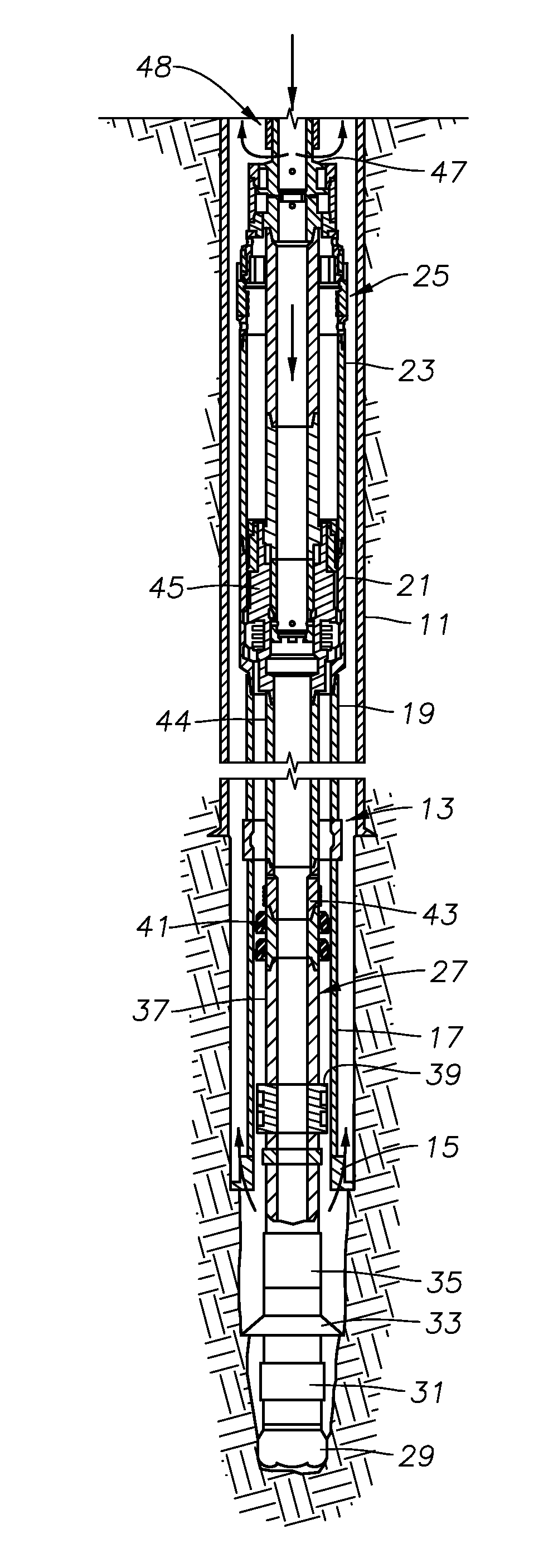
[0025]Referring to FIG. 1, a well is shown having a casing 11 that is cemented in place. An outer string 13 is located within casing 11 and extends below to an open hole portion of the well. In this example, outer string 13 is made up of a drill shoe 15 on its lower end that may have cutting elements for reaming out the well bore. A tubular shoe joint 17 extends upward from drill shoe 15 and forms the lower end of a string of liner 19. Liner 19 comprises pipe that is typically the same type of pipe as casing, but normally is intended to be cemented with its upper end just above the lower end of casing 11, rather than extending all the way to the top of the well or landed in a wellhead and cemented. The terms “liner” and “casing” may be used interchangeably. Liner 19 may be several thousand feet in length.

[0026]Outer string 13 also includes a profile nipple or sub 21 mounted to the upper end of liner 19. Profile nipple 21 is a tubular member having grooves and recesses formed in it f...


PUM


Abstract

A method of drilling a well and installing a liner includes assembling concentric inner and outer strings of tubulars. A drill bit is located at the lower end of the inner string and a liner with a liner hanger makes up part of the outer string. The inner and outer strings may be rotated in unison to drill the well. A valve is located upstream of a liner hanger control tool used to release and set the liner hanger in the drill string. The valve comprises a ported sleeve that slides relative to a ported housing to meter flow from the interior of the drill string to the annular space. The redirected flow maintains a minimum flow rate in the annular space to prevent cuttings from settling on the control tool. A portion of the valve can further be used with a dart to manipulate downstream equipment.

Description

FIELD OF THE INVENTION[0001]This invention relates in general to oil and gas well drilling while simultaneously installing a liner in the well bore.BACKGROUND OF THE INVENTION[0002]Oil and gas wells are conventionally drilled with drill pipe to a certain depth, then casing is run and cemented in the well. The operator may then drill the well to a greater depth with drill pipe and cement another string of casing. In this type of system, each string of casing extends to the surface wellhead assembly.[0003]In some well completions, an operator may install a liner rather than an inner string of casing. The liner is made up of joints of pipe in the same manner as casing. Also, the liner is normally cemented into the well. However, the liner does not extend back to the wellhead assembly at the surface. Instead, it is secured by a liner hanger to the last string of casing just above the lower end of the casing. The operator may later install a tieback string of casing that extends from the...

Claims


Application Information

Patent Timeline
Patent Type & Authority Applications(United States)
IPC IPC(8): E21B7/20E21B23/00E21B34/00E21B34/06E21B43/10E21B41/00
CPCE21B7/20E21B34/14E21B34/063E21B21/103B41J11/007B41J29/377G03G15/6573G03G21/20
Inventor NIKIFORUK, KEVIN JAMES
Owner SCHLUMBERGER TECH CORP
Why Eureka
Try Eureka