
Microfluidic, electrochemical devices

Inactive Publication Date: 2012-07-19
PRESIDENT & FELLOWS OF HARVARD COLLEGE
View PDF3 Cites 55 Cited by
  • Summary
  • Abstract
  • Description
  • Claims
  • Application Information

AI Technical Summary

Benefits of technology

[0036]attaching one or more porous, hydrophilic layer including a fluid-impermeable barrier that substantially permeates the thickness of the patterned porous, hydrophilic layer and defines a boundary of one or more hydrophilic channel(s) in the patterned porous, hydrophilic layer; and
[0037]disposing a second fluid-impermeable layer between adjacent patterned porous, hydrophilic layers; wherein the second fluid-impermeable layer includes one or more openings; and each opening is in alig

Problems solved by technology

Such devices are generally expensive, inflexible, and difficult to construct.

Method used


Image

  • Microfluidic, electrochemical devices
  • Microfluidic, electrochemical devices
  • Microfluidic, electrochemical devices

Examples


Embodiment Construction

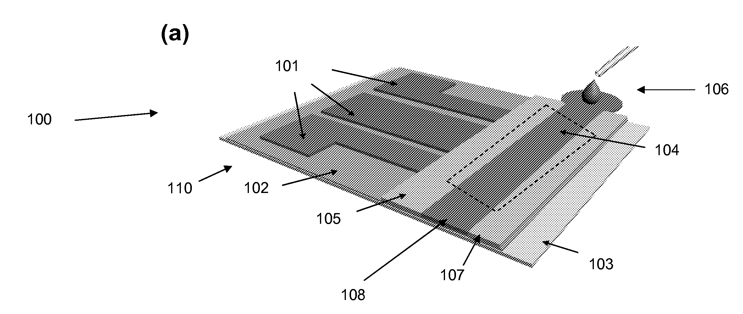
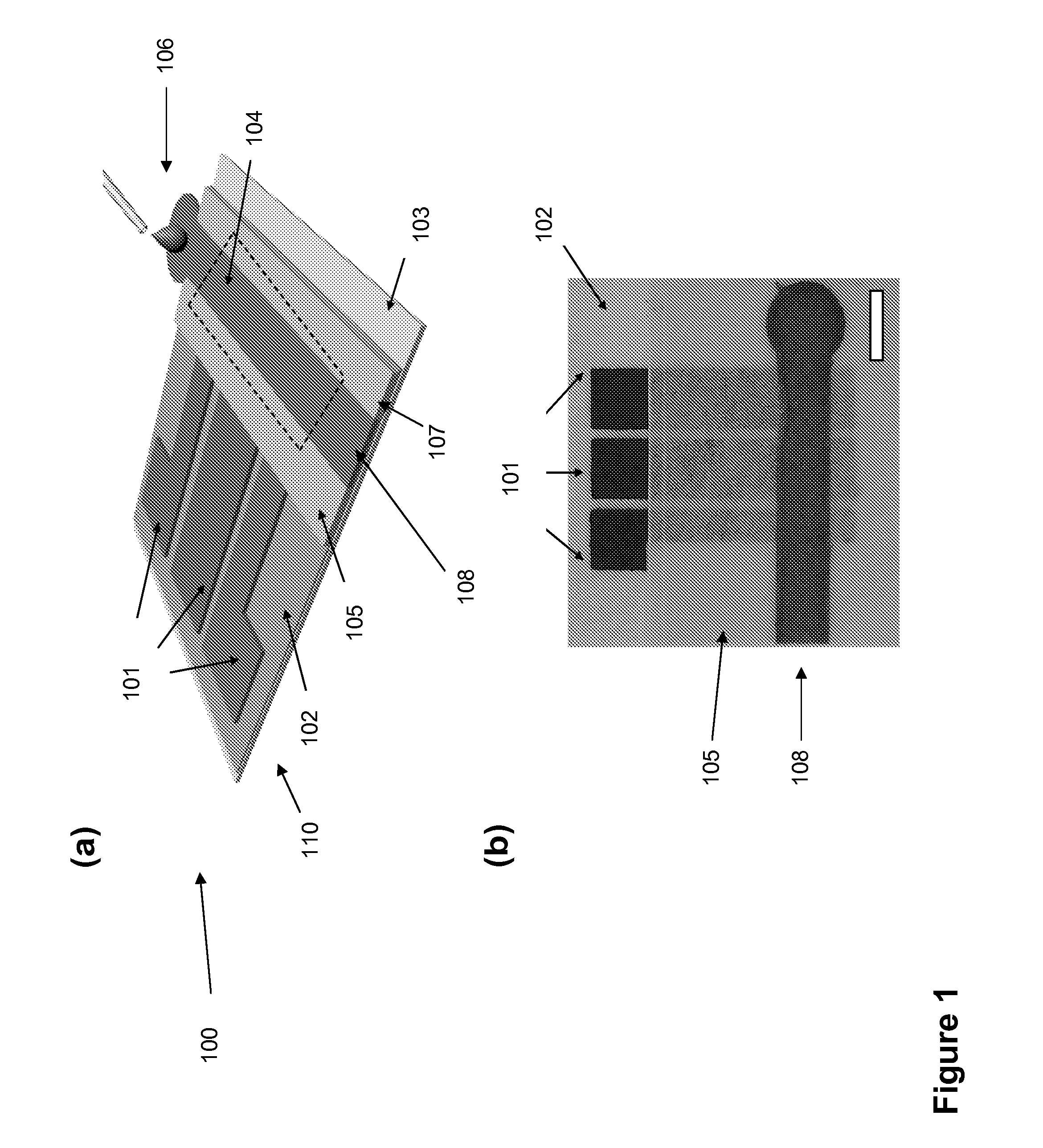
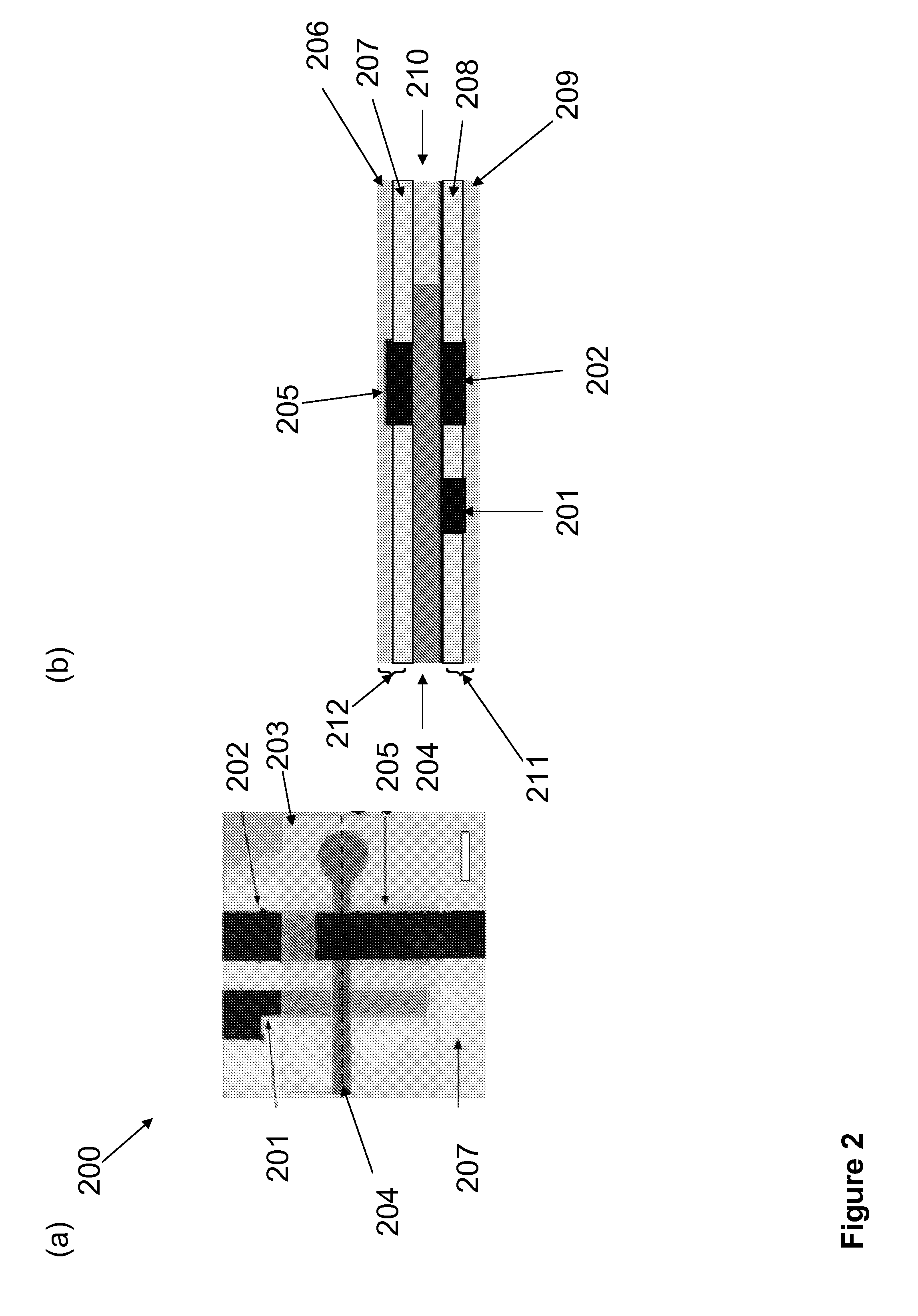
[0065]In one aspect, a microfluidic, electrochemical device is described. The microfluidic, electrochemical device comprises a first electrode assembly and a first porous, hydrophilic layer. The first electrode assembly comprises a first substrate layer which supports one or more electrode(s). In some embodiments, the microfluidic, electrochemical device further comprises a second electrode assembly comprising a second substrate layer which supports one or more electrode(s). In some embodiments, the first or second electrode assembly further comprises a barrier material surrounding at least a portion of the electrode. In some embodiments, the electrode is substantially surrounded by the barrier material. In some embodiments, the first or second substrate layer has a two-layer structure comprising a paper or plastic-film and a layer of the barrier material. In some specific embodiments, the barrier material comprises polymerized photoresist disposed on the supporting layer and substa...


PUM


Abstract

Microfluidic, electrochemical devices are described. The microfluidic, electrochemical device comprises one or more electrode(s) on a substrate and a patterned porous, hydrophilic layer having a fluid-impermeable barrier which substantially permeates the thickness of the porous, hydrophilic layer and defines boundaries of one or more hydrophilic channels within the patterned porous, hydrophilic layer, wherein the hydrophilic channel(s) comprises a hydrophilic region which is in fluidic communication with the electrode(s). In some embodiments, the electrodes comprise a working electrode, a counter electrode, and a reference electrode. In some embodiments, the microfluidic, electrochemical device further comprises a fluid sink. The method of assembling the microfluidic, electrochemical device is described. The method of using the device for electrochemical analysis of one or more analytes is also described.

Description

RELATED APPLICATIONS[0001]This application claims the benefit of U.S. Provisional Patent Application No. 61 / 158,251, filed Mar. 6, 2009, which is hereby incorporated by reference in its entirety. This application is related to copending PCT Application, titled “Methods Of Micropatterning Paper-Based Microfluidics,” filed on Mar. 8, 2010, Publication No. ______, which is incorporated in its entirety by reference.BACKGROUND[0002]The disclosed subject matter relates generally to microfluidic devices.[0003]In recent years, microfluidic systems have attracted increasing interests due to their diverse and widespread potential applications. For example, using very small volumes of samples, microfluidic systems could carry out complicated biochemical reactions to acquire important chemical and biological information. Among other advantages, microfluidic systems reduce the required amount of samples and reagents, shorten the response time of reactions, and decrease the amount of biohazard wa...

Claims


Application Information

Patent Timeline
IPC IPC(8): G01N27/26G01N27/416
CPCB01L3/502B01L3/5027G01N27/3272B01L2300/0887B01L2300/0645
Inventor WHITESIDES, GEORGE M.NIE, ZHIHONGNIJHUIS, CHRISTIANCHEN, XINMARTINEZ, ANDRES W.NAROVLYANSKY, MAX
Owner PRESIDENT & FELLOWS OF HARVARD COLLEGE
Learn More