Wireless communication system, base station apparatus, mobile station apparatus, and communication method

a communication system and wireless technology, applied in the field of wireless communication system, a mobile station apparatus, can solve the problems of increased process in the mobile station apparatus, waste of radio resources and electric power, and degradation of the utilization efficiency of communication resources, so as to reduce the amount of information required, suppress the effect of increasing power consumption and effective utilization of radio resources

Inactive Publication Date: 2012-07-19
SHARP KK
View PDF8 Cites 30 Cited by
  • Summary
  • Abstract
  • Description
  • Claims
  • Application Information

AI Technical Summary

Benefits of technology

[0027]Considering the above problems, it is an object of the present invention to provide a wireless communication system, a base station apparatus, a mobile station apparatus, and a communication method which avoids problems such as degradation of usage efficiency of communication resources or increase of processes in the mobile station apparatus by making it easier to grasp the number and arrangement of mobile stations in a service cell requesting reception of an MBMS.
[0058]According to the present invention, since a mobile station apparatus requesting an MBMS adds intra-cell information of its own to a response message to a message and transmits the response message added with the intra-cell location information to a base station apparatus, it becomes possible to provide an appropriate MBMS based on the intra-cell location of the mobile station apparatus, enabling effective utilization of radio resources thereby. In addition, since the process required in the mobile station apparatus only adds to the Counting response a signal based on reception power of the downlink reference signal which has always been being measured and uses it to select a providing method in the Notification, increase of power consumption can be suppressed without requiring a complicated process. Furthermore, it also becomes possible to provide optimal transmission parameters even if there are many mobile station apparatuses requesting service in the vicinity of the cell center.

Problems solved by technology

However, although provision of service is performed via PTM based on the number of mobile station apparatuses 1 when there are mobile station apparatuses 1A, 1B and 1C in the vicinity of the cell center, and a mobile station apparatus 1D at the cell edge as shown in FIG. 13 (hereinafter mobile station apparatuses (1A to 1D) are expressed as mobile station apparatuses 1), it is necessary to perform transmission with a modulation / encoding scheme robust to noise and a high electric power so that even the mobile station apparatus 1D at the cell edge can receive, which may result in wasted radio resources and electric power.
However, the approach uses the MBMS transmitted via PTM using a large amount of communication resources only for grasping the number and arrangement of the mobile station apparatuses 1 in the service cell requesting reception of the MBMS, resulting in problems such as degradation of usage efficiency of communication resources or increase of processes in the mobile station apparatuses 1.

Method used


Image

  • Wireless communication system, base station apparatus, mobile station apparatus, and communication method
  • Wireless communication system, base station apparatus, mobile station apparatus, and communication method
  • Wireless communication system, base station apparatus, mobile station apparatus, and communication method

Examples


first embodiment

[0072]A first embodiment of the present invention will be explained below, referring to FIGS. 1 to 9.

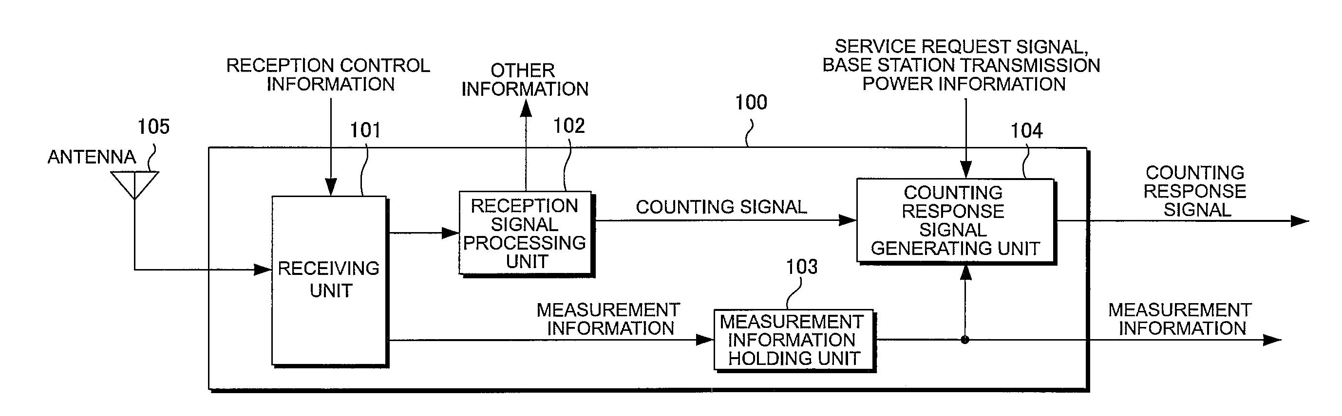
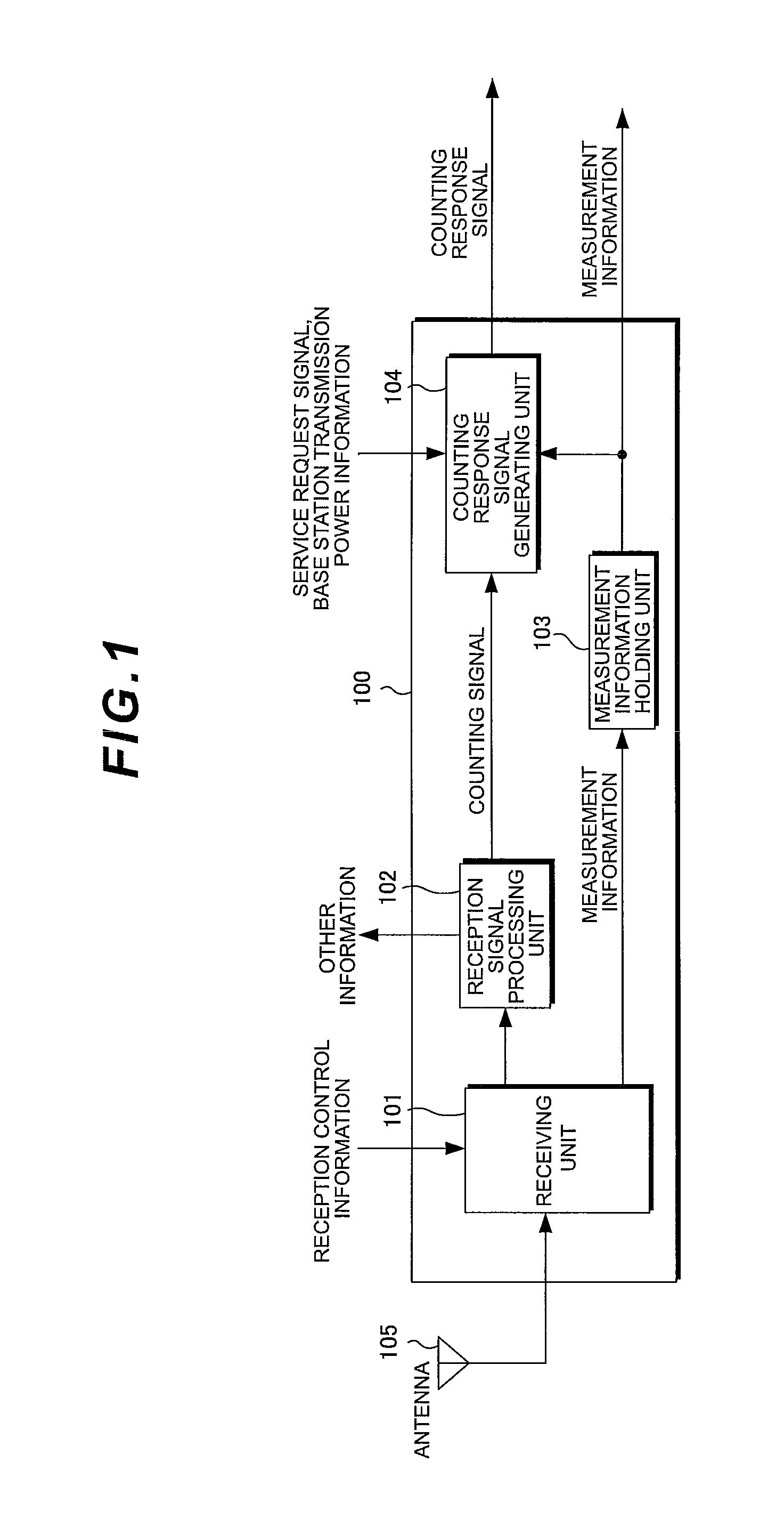
[0073]FIG. 1 is a block diagram illustrating an exemplary receiving device of a mobile station apparatus (expressed as UE in the following) 1 according to an embodiment of the present invention. The receiving device 100 includes a receiving unit 101, a reception signal processing unit 102, a measurement information holding unit 103, a Counting response signal generating unit 104, and an antenna 105. A reception signal (transmission signal from the base station apparatus (expressed as eNB in the following) 3) is received in the receiving unit 101 via the antenna 105.

[0074]In the receiving unit 101, the reception signal is demodulated based on reception control information indicating the channel schedule. The reception control information includes information related to demodulation such as reception timing with regard to each channel, multiplexing method, resource allocation informati...

second embodiment

[0106]In the above-mentioned first embodiment, a case has been described where a signal indicating the intra-cell location is included in the Counting response from the UE1. The present embodiment describes a case where threshold information related to the intra-cell location of the UE1 is included in the Counting so that can request a Counting response to the UE1. The eNB3 and the UE1 of the present embodiment respectively have the same configurations as those shown in FIGS. 1, 2, 3, and 4 of the first embodiment.

[0107]Counting and determination of the providing method in the present embodiment will be described in detail. In the present embodiment, threshold information of the intra-cell location for determining whether or not the UE1 newly transmits a Counting response is added to the conventional Counting. The threshold information is, for example, information indicating “report when the path loss value is not less than a certain threshold value” and “report when the path loss v...

third embodiment

[0112]In the above-mentioned second embodiment, a case has been described where threshold information of the intra-cell location of the UE1 is included so that the NW 601 requests a Counting response to the UE1. The present embodiment describes a case where the NW 601 includes a plurality of different Probability factors in the intra-cell location of the UE1. The eNB3 and the UE1 of the present embodiment respectively have the same configurations as those shown in FIGS. 1, 2, 3, and 4 of the first embodiment.

[0113]Counting and determination of the providing method in the present embodiment will be described in detail. In the present embodiment, the types of Probability factors to be included in MBMS ACCESS INFORMATION are increased. One is the Probability factor used when the loss value is not less than a certain threshold value, and one is the Probability factor used when the path loss value is less than a certain threshold value. In addition, the threshold may be included in MBMS ...


PUM


Abstract

To perform MBMS transmission capable of effective utilization of resources without increasing load in a mobile station apparatus. In a wireless communication system including a base station apparatus and mobile station apparatuses to provide an MBMS (Multimedia Broadcast Multicast Service), the base station apparatus transmits a message for aggregating the number of mobile station apparatuses requesting an MBMS to a mobile station apparatus being served, and, among the mobile station apparatuses, the mobile station apparatus requesting an MBMS adds intra-cell location information of its own to a response message to the message and transmits the response message added with the intra-cell location information to the base station apparatus.

Description

TECHNICAL FIELD[0001]The present invention relates to a wireless communication system, a base station apparatus, a mobile station apparatus, and a communication method which perform communication using a plurality of subcarriers, and particularly to a communication method of an MBMS (Multimedia Broadcast Multicast Service).BACKGROUND ART[0002]Evolved Universal Terrestrial Radio Access (hereinafter referred to as EUTRA) which has evolved the third generation mobile communication system in the 3GPP (3rd Generation Partnership Project), and Advanced EUTRA (also called LTE-Advanced, and hereinafter referred to as A-EUTRA) which is a further development thereof are under study (see Non-patent document 1).[0003]FIG. 12 illustrates an exemplary configuration of a downlink radio frame in EUTRA. In FIG. 12, a radio frame is shown with the time axis being the horizontal axis and the frequency axis being the vertical axis. A unit of the radio frame is composed of dividing the frequency axis in...

Claims


Application Information

Patent Timeline
IPC IPC(8): H04W4/06H04H20/71
CPCH04L12/189H04W4/021H04W4/06H04N21/6405H04W72/005H04N21/6131H04W52/0241Y02D30/70H04W72/30
Inventor TSUBOI, HIDEKAZUUEMURA, KATSUNARINAKASHIMA, DAIICHIRO
Owner SHARP KK
Why Eureka
Try Eureka