

Image decoding apparatus, image decoding method, image coding apparatus, and image coding method
Patent Information
- Authority / Receiving Office
- US · United States
- Current Assignee / Owner
- SOVEREIGN PEAK VENTURES LLC
- Publication Date
- 2012-07-19
- Estimated Expiration
- Not applicable · inactive patent
Smart Images
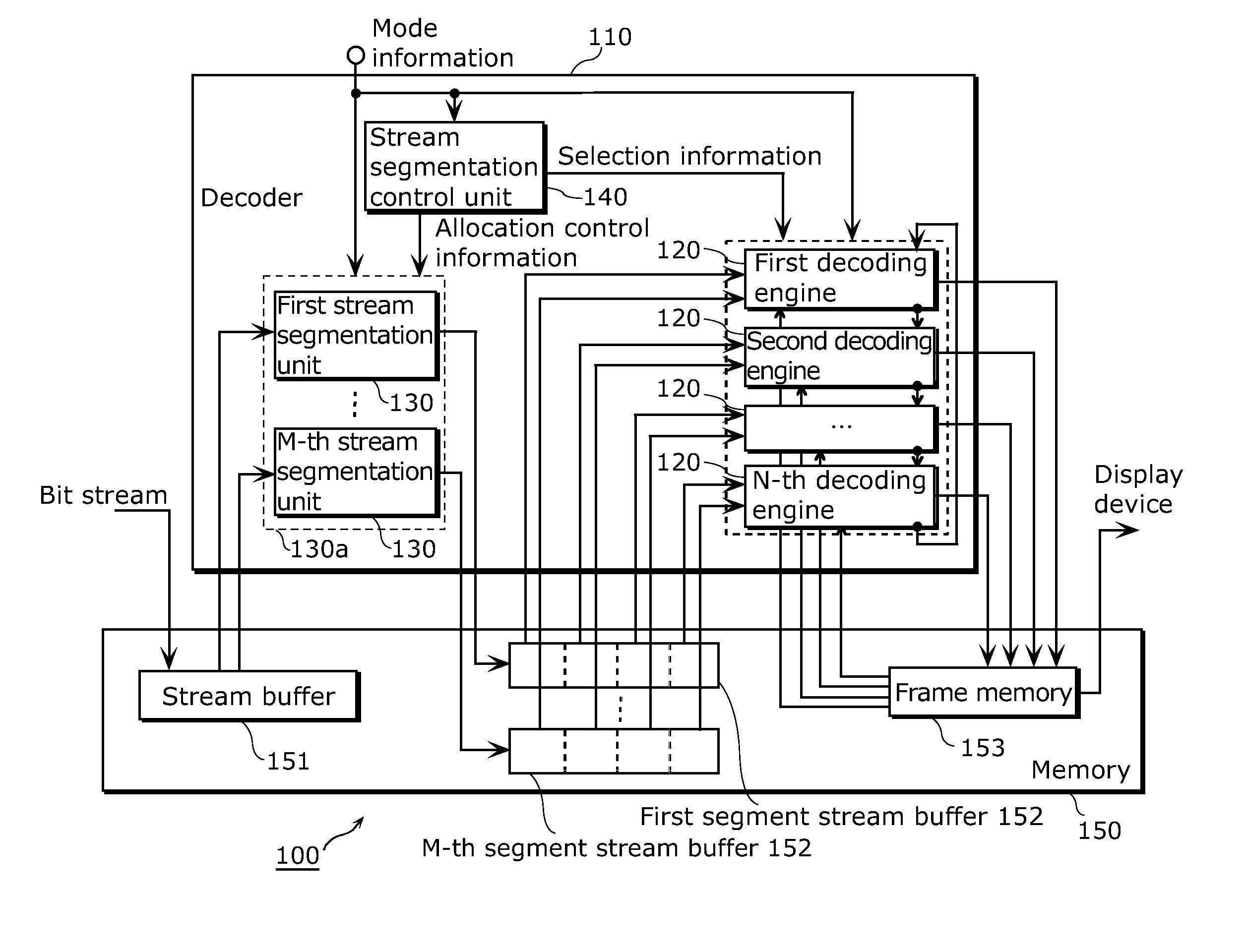
Figure 1 
Figure 2 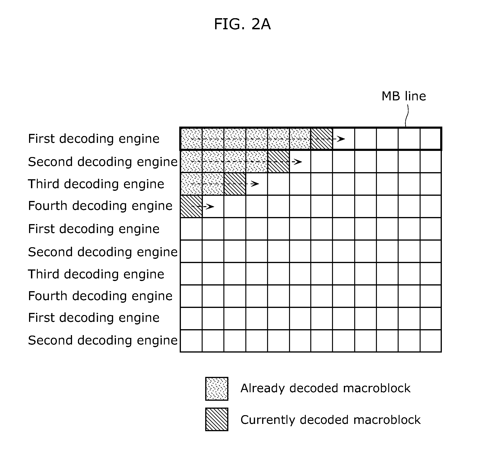
Figure 3
Abstract
Description
TECHNICAL FIELD
[0001] The present invention relates to an image decoding apparatus and an image decoding method for decoding a bit stream generated by coding image data, and an image coding apparatus and an image coding method for generating a bit stream by coding image data. The present invention particularly relates to an image decoding apparatus and an image decoding method for executing decoding in parallel, and an image coding apparatus and an image coding method for executing coding in parallel.BACKGROUND ART
[0002] An image coding apparatus for coding a moving picture segments each picture constituting the moving picture into macroblocks, and codes the moving picture on a macroblock basis. The image coding apparatus thus generates a bit stream representing the coded moving picture.
[0003] FIG. 44 is a diagram showing a structure of a picture to be coded.
[0004] The picture is segmented into macroblocks composed of 16×16 pixels, and coded. Here, a plurality of macroblocks included in...