Closing means

a technology of means and means, applied in the direction of caps, rotating screw stopper insertion, application, etc., can solve the problems of high cost, large retrofitting measures, and drive types that require extensive retrofitting measures, and achieve the effect of high flexibility

Inactive Publication Date: 2012-07-26
KRONES AG
View PDF6 Cites 58 Cited by
  • Summary
  • Abstract
  • Description
  • Claims
  • Application Information

AI Technical Summary

Benefits of technology

[0005]One aspect of the disclosure thus is to provide a closing means which, in a structurally simple manner, offers higher flexibility when it comes to fulfill the customers' requests for the closing means.

Problems solved by technology

Moreover, this type of drive requires extensive retrofitting measures if special customer requests must be considered.
This, however, is extremely cost-intensive.

Method used


Image

  • Closing means
  • Closing means
  • Closing means

Examples


Embodiment Construction

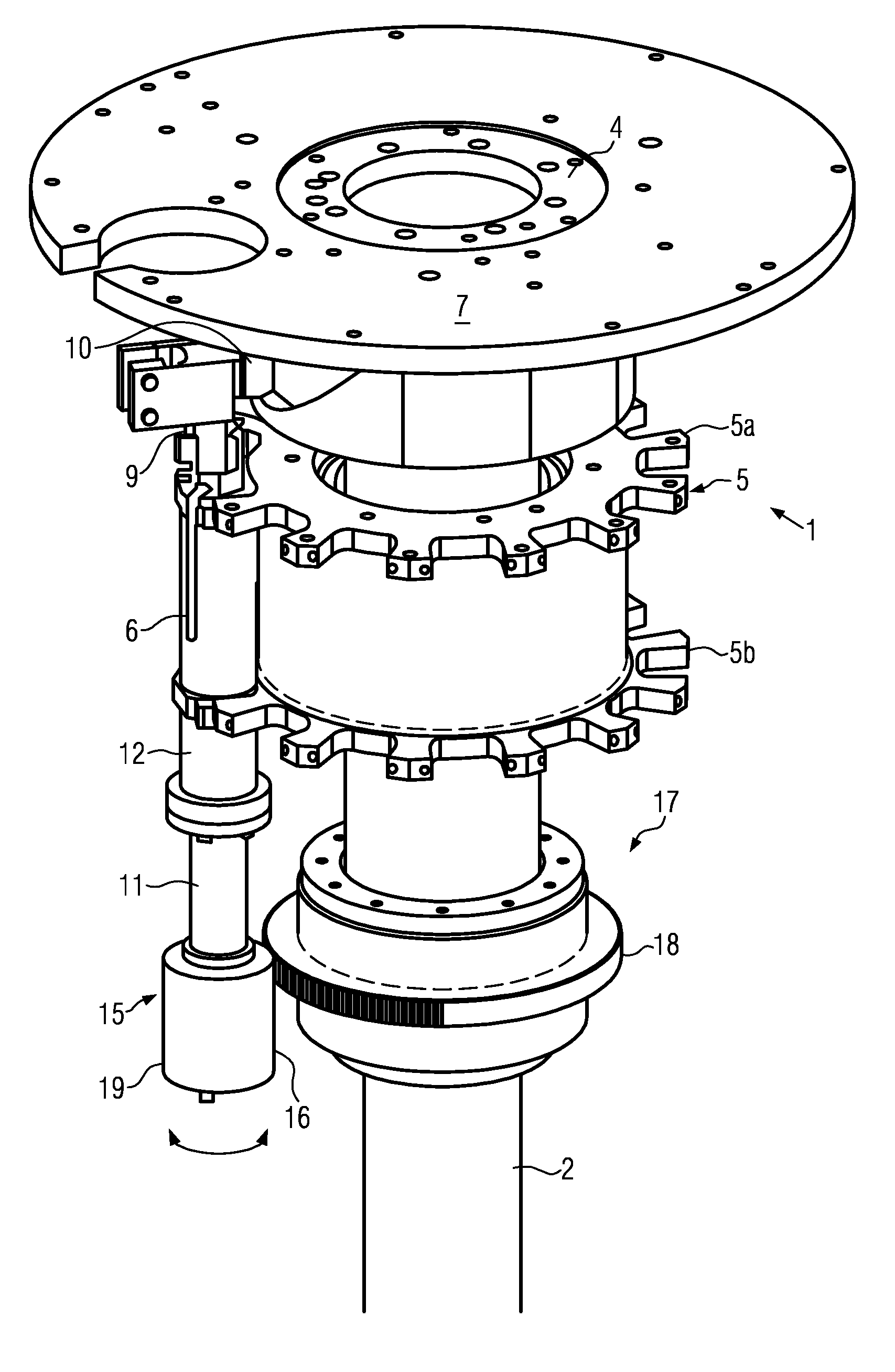
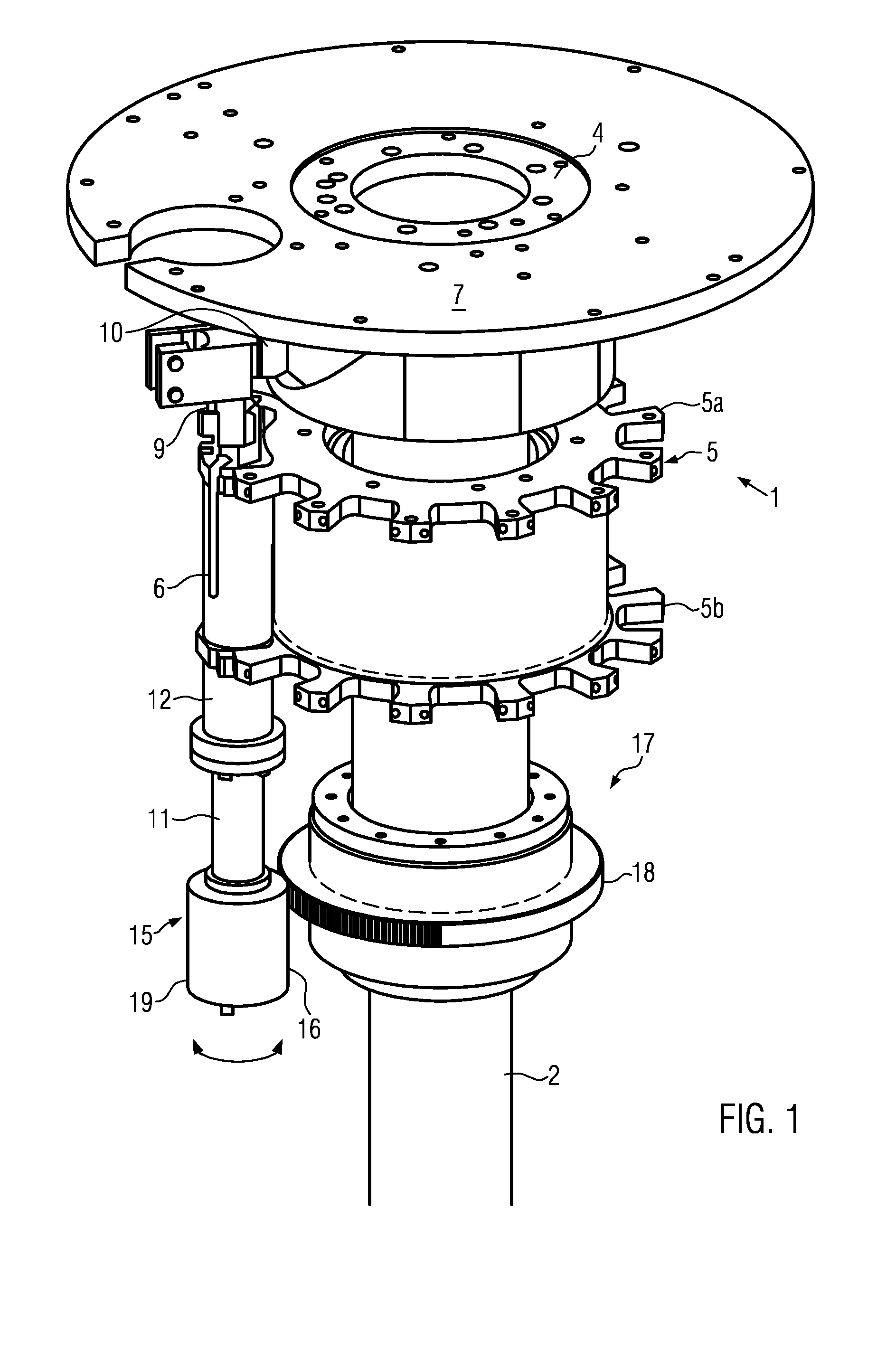
[0019]FIG. 1 shows, in a perspective schematic partial representation, a closing means 1 of an essentially conventional design. The closing means 1 contains a vertical central column 2 which comprises an inner, not generally, but vertically stationary support 3, and an outer rotary sleeve 4 driven about its vertical central line 4′. The mountings for the containers and a mounting 5 for at least one closing unit 6 are fixed on the rotary sleeve 4 in a common, not shown way. The mounting 5 in the represented embodiment contains two partial circles 5a and 5b lying one upon the other and keeping the closing units 6 at a peripheral distance with respect to each other.

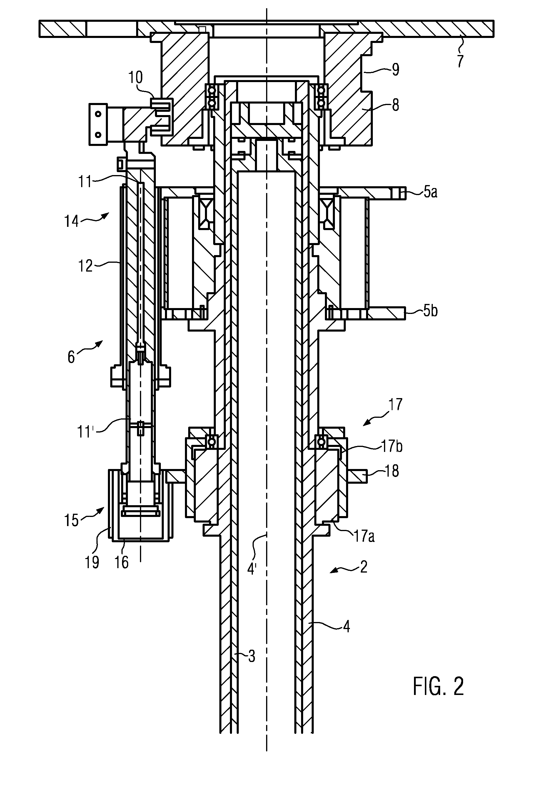
[0020]Above the central column 2, a stationary head plate 7 is provided at which a cam curve 9 is arranged at a flange 8 projecting downwards, into which cam curve a guide roller 10 engages in a known manner, the guide roller being rotatably mounted at the closing unit 6. A lifting cylinder 11 is connected with the guide rol...


PUM


Abstract

A closing means for containers including a transport means for the containers having a drive and at least one closing unit for applying a closure by a linear motion along a central line and a rotary motion about the central line, wherein the rotary motion is applied by rolling off two gear members. To achieve a structurally simple and flexible embodiment the first one of the gear members is connected with a separate drive independent of the drive of the transport means.

Description

CROSS-REFERENCE TO RELATED APPLICATION[0001]The present application claims the benefit of priority of German Application No. 102011003118.9, filed Jan. 25, 2011. The entire text of the priority application is incorporated herein by reference in its entirety.FIELD OF THE DISCLOSURE[0002]The disclosure relates to a closing means for containers, such as used in beverage bottling operations.BACKGROUND[0003]Such a closing means is known, for example, from EP-A-1 103 513.The known closing means is part of a bottling plant for beverage containers, in particular bottles, and contains a bearing central column which is driven by a drive to rotate about a vertical axis. Mountings for the containers and one closing unit each allocated to each mounting and rotating about the vertical axis together with the central column are arranged at the central column. In the region of the closing units, a stationary frame is furthermore provided at which a cam curve is fixed on which the closing unit rolls ...

Claims


Application Information

Patent Timeline
Patent Type & Authority Applications(United States)
IPC IPC(8): B67B3/20
CPCB67B3/2033B67B3/18
Inventor SCHLIEPER, ULRICH
Owner KRONES AG
Why Eureka
Try Eureka