
Coolant control and wiper system for a continuous casting molten metal mold

a technology of cooling fluid and mold, which is applied in the direction of casting plants, ingot casting plants, manufacturing tools, etc., can solve the problems of cooling fluid supplied, expansion back, re-melting of solidifying surface of castparts, cooling and solidification of the core of castparts,

Active Publication Date: 2012-07-26
WAGSTAFF INC
View PDF2 Cites 5 Cited by
  • Summary
  • Abstract
  • Description
  • Claims
  • Application Information

AI Technical Summary

Benefits of technology

This patent is about a coolant control and wiper system for a continuous casting molten metal mold. The invention is about improving the cooling and solidification process of the metal in the mold by controlling the rate at which the starting block is lowered. The invention also includes a retractable feature for better system control and a mold table assembly that can be tilted for easier handling of the mold. The invention is applicable to various metals and metal casting technologies.

Problems solved by technology

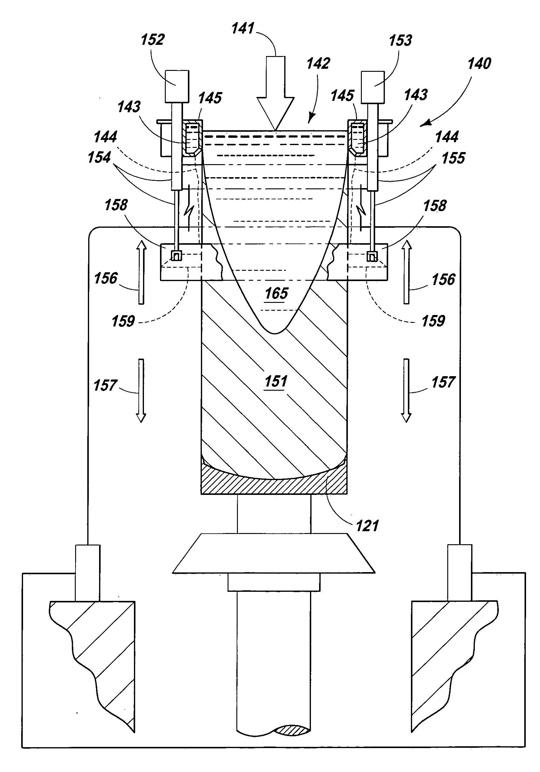
The shrinkage of the castpart then causes the solidifying castpart to shrink back away from the cooler mold wall, resulting in some re-melting of solidifying surface of the castpart and expansion back to the mold wall.
The volume of cooling fluid supplied to the emerging castpart can be significant and if left uncontrolled, it will run down the side of the outer surface of the castpart and cause further cooling and solidification of the core of the castpart.
This results in internal stresses being imposed between the various internal locations in the castpart and may result in undesirable imperfections and defects.
If the excess cooling fluid is not sufficiently controlled and runs down the side of the cooling castpart, it causes unwanted additional cooling of the core of the castpart and impedes the desired annealing process in the castpart.
At or near the start up of these traditional systems, the solidifying castpart would pass through the wipers but there is a time when extra water would become trapped between a wiper, starting block or head and the castpart for a period of time (normally minutes).
This additional water at startup results in increased and undesirable cooling of the castpart and may also allow cooling fluid to get into the starting block area and increase the probability of a crack forming at or near the butt portion of the castpart during or after solidification.
It is costly to have to scrap an entire casting due to a crack in the butt portion of the ingot or castpart.

Method used


Image

  • Coolant control and wiper system for a continuous casting molten metal mold
  • Coolant control and wiper system for a continuous casting molten metal mold
  • Coolant control and wiper system for a continuous casting molten metal mold

Examples


Embodiment Construction

[0041]Many of the fastening, connection, manufacturing and other means and components utilized in this invention are widely known and used in the field of the invention described, and their exact nature or type is not necessary for an understanding and use of the invention by a person skilled in the art or science; therefore, they will not be discussed in significant detail. Furthermore, the various components shown or described herein for any specific application of this invention can be varied or altered as anticipated by this invention and the practice of a specific application or embodiment of any element may already be widely known or used in the art or by persons skilled in the art or science; therefore, each will not be discussed in significant detail.

[0042]The terms “a”, “an”, and “the” as used in the claims herein are used in conformance with long-standing claim drafting practice and not in a limiting way. Unless specifically set forth herein, the terms “a”, “an”, and “the”...


PUM

PropertyMeasurementUnit
elevationsaaaaaaaaaa
pressureaaaaaaaaaa
permeableaaaaaaaaaa

Abstract

A coolant or wiper control system for use in continuous casting mold for controlling and managing the coolants interaction with the castpart during casting. In some aspects of the process, the wiper framework is started sufficiently away from the bottom block so as not to interfere or cause / allow coolant to get into the bottom block; is then rapidly moved back to the emerging castpart during transient heat-up; and then moved away from the mold with the solidified castpart at a controlled rate to a predetermined steady state position or to a second transitory state of the casting.

Description

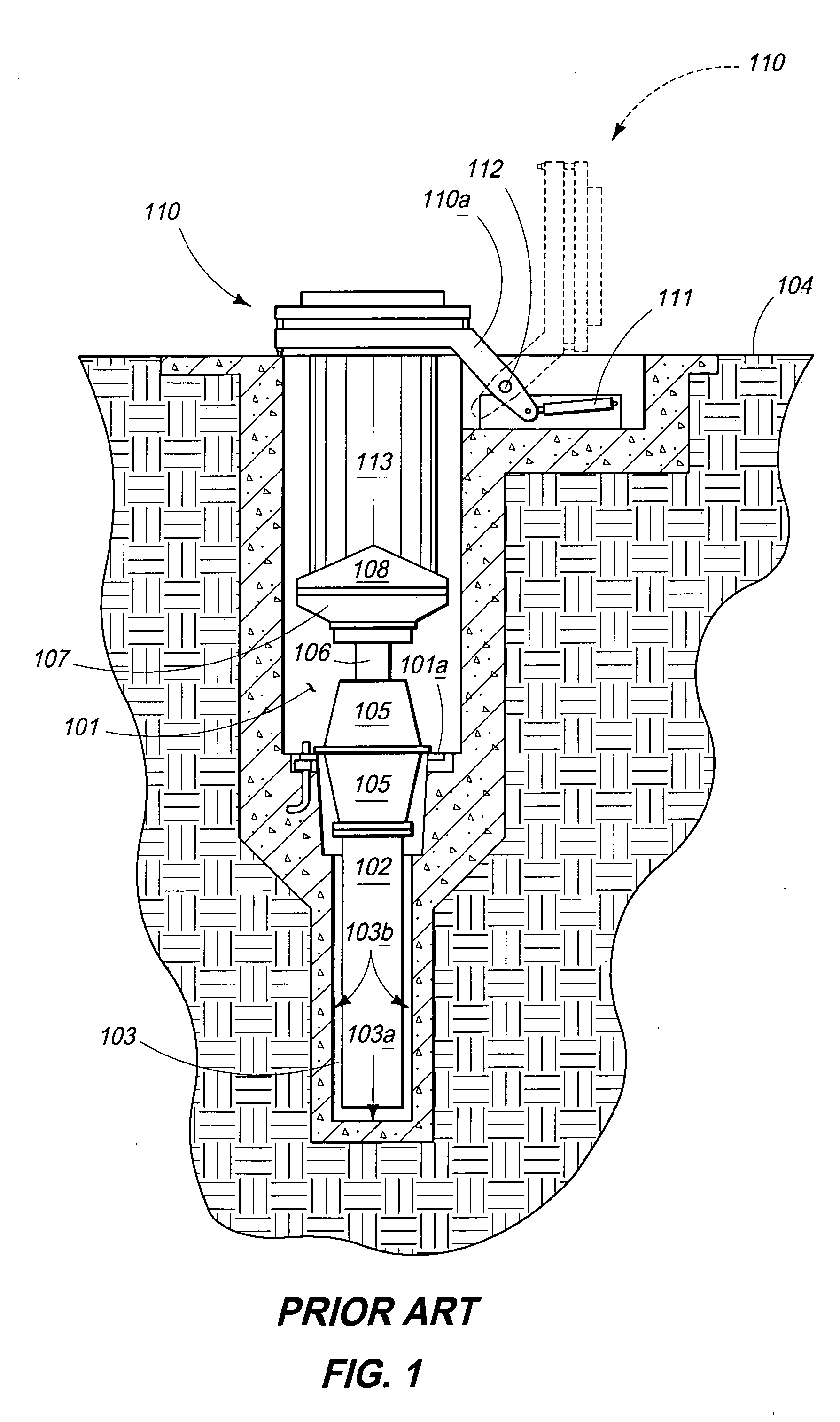
CROSS REFERENCE TO RELATED APPLICATION[0001]This application does not claim priority from any other application.TECHNICAL FIELD[0002]This invention pertains to coolant control and wiper system for use in a continuous casting molten metal mold, which may include positional wiper management and a retractable feature for better system control.BACKGROUND OF THE INVENTION[0003]Metal ingots, billets and other castparts may be formed by a casting process which utilizes a vertically oriented mold situated above a large casting pit beneath the floor level of the metal casting facility, although this invention may also be utilized in horizontal molds. The lower component of the vertical casting mold is a starting block. When the casting process begins, the starting blocks are in their upward-most position and in the molds. As molten metal is poured into the mold bore or cavity and cooled (typically by water), the starting block is slowly lowered at a pre-determined rate by a hydraulic cylinde...

Claims


Application Information

Patent Timeline
Patent Type & Authority Applications(United States)
IPC IPC(8): B22D11/124B22D11/16
CPCB22D11/1248B22D11/049B22D9/00B22D7/005B22D11/055B22D11/06B22D11/22
Inventor SHABER, CRAIG
Owner WAGSTAFF INC
Learn More