Multi-Tasking Rod Guide

a multi-tasking, rod guide technology, applied in the direction of drilling casings, borehole/well accessories, drilling pipes, etc., can solve the problems of affecting the life cycle affecting the upward flow of hydrocarbons, and affecting the production efficiency of the rod guide, so as to increase the demand for energy consumption and less abrasion

Active Publication Date: 2012-07-26
DICKINSON DOUGLAS RAY
View PDF3 Cites 3 Cited by
  • Summary
  • Abstract
  • Description
  • Claims
  • Application Information

AI Technical Summary

Benefits of technology

[0018]It is also an object and advantage of the present invention that a multi-tasking rod guide is disclosed that not only handily performs the centering function known in the art, but also affords auxiliary pumping to supplement upwardly pumping of hydrocarbons from the well-bottom and inherently imparts less abrasion on the contact surfaces of production string and casing walls, respectively.
[0019]It is also an object and advantage of the present invention that embodiments simultaneously perform a plurality of functions without substantially increasing the demand for consumption of energy.

Problems solved by technology

It is well known that such conventional rod guides suffer from excessive wear and abrasion under the influence of upwardly streaming high-pressure hydrocarbons.
Such hydrocarbon streams typically include abrasive solid materials such as sand and debris which drastically undermine rod guide life cycle particularly because these occluded materials are moving at high speed.
In addition, these solids and other troublesome materials appreciated tend to inhibit the upwards hydrocarbon flow.
These and other known deficiencies in the rod guide art have continued to render sustaining continuous flow of hydrocarbons from subsurface formations via downhole pumping systems upwardly to the well surface elusive to remedy, and unduly expensive in view of the necessity to frequently conduct rod guide maintenance because of inherently short life cycles and substantial consumption of energy to sustain demanding pumping requirements.

Method used


Image

  • Multi-Tasking Rod Guide
  • Multi-Tasking Rod Guide
  • Multi-Tasking Rod Guide

Examples


Embodiment Construction

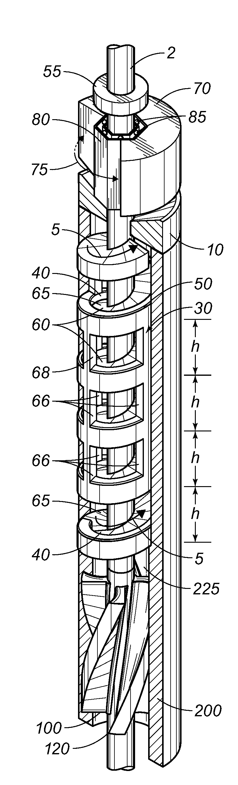
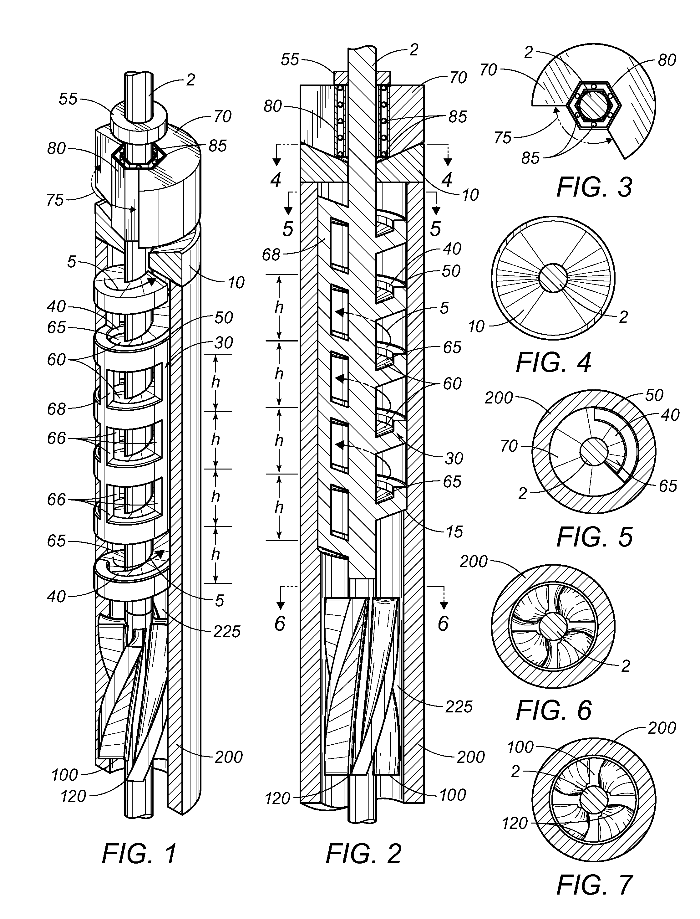
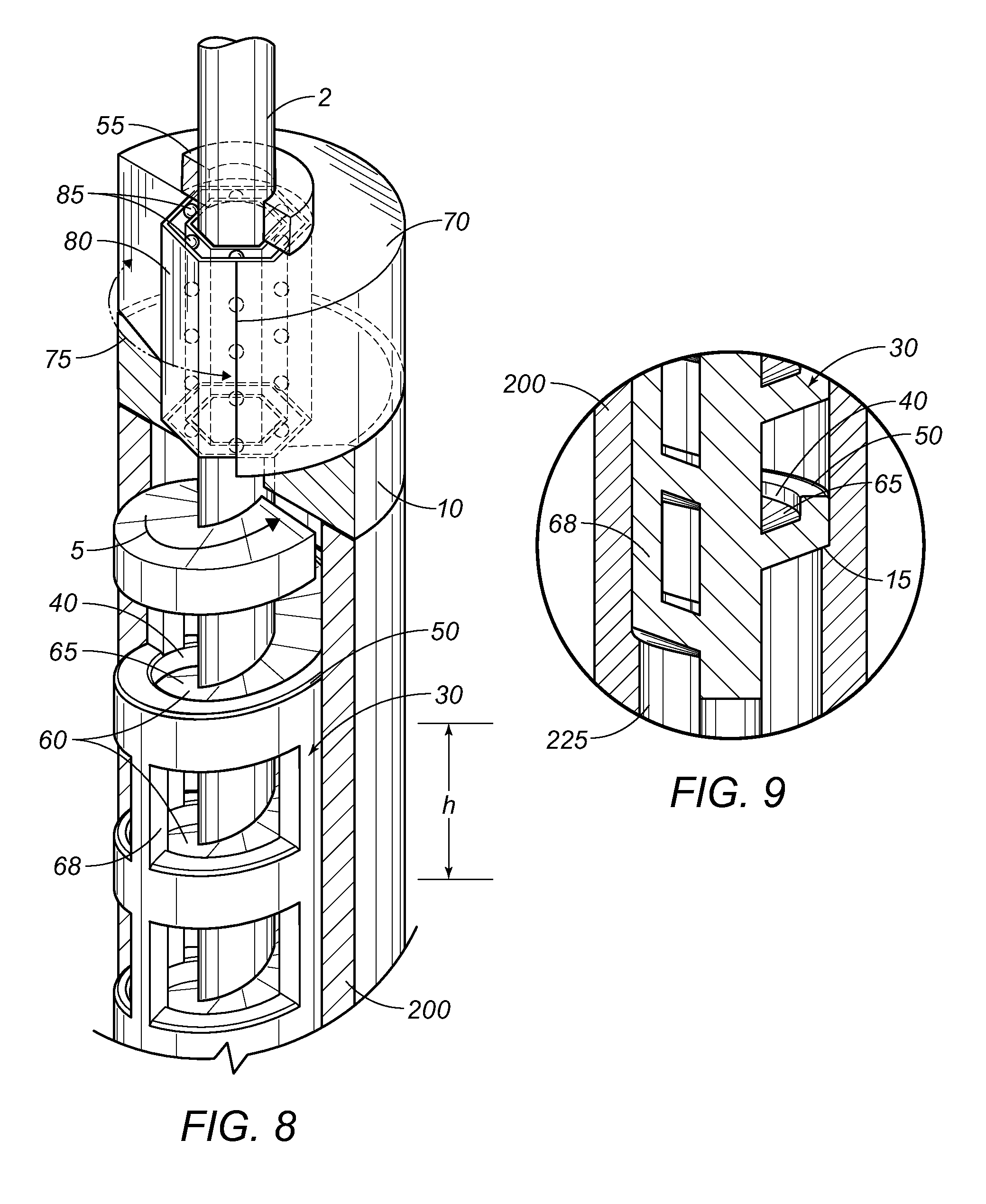
[0030]Reference is made herein to the figures in the accompanying drawings in which like numerals refer to like components. Table 1 enumerates the assigned numerals.

TABLE 1Rod Guide Component Listing#Component NameStructure / FunctionRemarks2pump rodaxial5hydrocarbon streamflowing upward toward surfacehigh-pressure stream10rod guidemulti-functional15overlap-portionoverlaps casing internal wall per cut-out30helical portionelongatecontinuously rotating40trough-like channelmanifest on each successive helical level45entry point at bottomentry into channel at bottom (lowest level)50beveldisposed on backside of helixavoid contacting tubing55plurality of detentslimits movement of backflow preventerhinter-level heightbetween each successive helical level60plurality of platescollection surface at each level65collection plateat each levelexcept top level66plurality of pillars4 per level; strengthens each level68pillarat each level70top collection plateat top level onlythicker for stability75ope...


PUM


Abstract

A multi-tasking downhole rod guide for centralizing a downhole pump rod production tubing within production tubing, while simultaneously reducing abrasion and deterioration of the production tubing and engendering auxiliary pump-boosting functions—with minimal energy consumption. The rod guide is configured with an elongate helix having a continuous trough-like channel through hydrocarbons flow upwardly under high pressure. As the pressurized hydrocarbons flow through a succession of plates at each equidistant helical level, the elongate helix rotates synchronously with the upwardly flowing hydrocarbons within the production tubing string. A multi-tasking downhole rod guide for centralizing downhole production tubing within a well casing, while simultaneously reducing abrasion and deterioration of the tubing and engendering auxiliary pump-boosting functions—with minimal energy consumption. The rod guide is configured with an elongate helix at each equidistant level which rotates in synchronization with the production string.

Description

RELATED APPLICATIONS[0001]This application claims priority based upon U.S. Provisional Application Ser. No. 61 / 471,196 filed Apr. 3, 2011.FIELD OF THE INVENTION[0002]The present invention relates to a downhole rod guide apparatus, and more particularly relates to an apparatus for performing a rod guide centralizer function downhole within a well bore, while simultaneously performing tubing-abrasion-reduction and auxiliary pump-boosting functions, with concomitant minimal energy consumption.BACKGROUND OF THE INVENTION[0003]There have been developed several downhole rod guides for sustaining the centralized disposition of a pumping rod within a string of production tubing. It is well known that such conventional rod guides suffer from excessive wear and abrasion under the influence of upwardly streaming high-pressure hydrocarbons. Such hydrocarbon streams typically include abrasive solid materials such as sand and debris which drastically undermine rod guide life cycle particularly be...

Claims


Application Information

Patent Timeline
Patent Type & Authority Applications(United States)
IPC IPC(8): E21B17/10
CPCE21B43/126E21B17/1071
Inventor DICKINSON, DOUGLAS RAY
Owner DICKINSON DOUGLAS RAY
Why Eureka
Try Eureka